Learning Hub
Glossary
Axial Load
An axial load is a force applied along the longitudinal axis of a structural member—such as a column, bolt, screw, or beam—either pulling it apart in tension or pushing it together in compression. The defining feature of an axial load is that it acts directly in line with the axis of the component, without introducing bending or twisting effects.
There are two main types of axial load. A tensile axial load is a pulling force that stretches or elongates the member along its axis, such as the tension present in a bolt that clamps two plates together. A compressive axial load is a pushing force that shortens or compresses the member, as seen in a vertical column carrying the weight of the structure above it.

When a member is subjected to an axial load, the stress is distributed uniformly across its cross-sectional area, assuming the load is perfectly centered. This axial stress is expressed as stress (σ) equals the applied load (P) divided by the cross-sectional area (A). If the load is not centered, a condition known as eccentric loading, bending stresses are introduced along with axial stress, which can decrease the stability and strength of the component.
Examples of axial loads are found in many engineering applications. Bolts and screws experience axial tension when tightened to hold components together. Columns and struts carry axial compressive loads from the weight of structural systems they support. Tie rods resist axial tensile loads to maintain the position of structural elements. Anchors may experience either tensile or compressive axial loads depending on how they are used.
Bolt Preload
Bolt preload is the tension, or stretch, intentionally created in a bolt when it's tightened. This tension generates a powerful clamping force between the bolt's head (or nut) and the materials being joined. By stretching the bolt like a spring, the tightening process creates a tensile force within the bolt and an opposing compressive force on the joint, effectively holding the parts together securely. This "built-in" clamping force is crucial for ensuring a joint remains stable and reliable, resisting external stresses like vibration, shear forces, and thermal expansion.
The proper application of bolt preload is essential for several reasons. It prevents loosening by keeping joints secure even under dynamic loads and vibrations. Preload also ensures that external forces are distributed evenly between the bolt and the joint, protecting the bolt from bearing the entire load. This stress distribution helps to avoid fatigue failure, significantly improving the bolt's lifespan. Additionally, in applications involving gaskets, preload is vital for compressing the gasket to create a leak-proof seal.

Several factors influence the amount of preload a bolt achieves. While applied torque is the most common method for creating preload, its effectiveness can be inconsistent due to friction. Lubrication plays a significant role, as it reduces friction at the threads and under the bolt head, allowing more of the applied torque to be converted into clamping force. The bolt's material and geometry also matter, as stronger bolts can withstand higher preloads without yielding. Finally, different tightening methods, such as angle tightening or direct tensioning, can offer more precise control over the resulting preload than simple torque application.
Clamp Load (or Preload) and Clamping Force
The terms clamp load and clamping force are closely related and often used interchangeably, but there’s a subtle distinction in how they’re defined and measured within fastener mechanics.
Clamp load refers to the tensile force generated in a fastener (such as a bolt or screw) when it is tightened. It is the internal tension that develops as the bolt stretches elastically, much like a spring being pulled. This stored tension is what creates the compressive force between the joined parts. In other words, clamp load is the result of tightening torque applied to the fastener.

Clamping force, on the other hand, refers to the compressive force acting on the joint members themselves—the pressure that holds the components together. It’s the external manifestation of the bolt’s internal clamp load. In a properly designed joint, the clamp load and clamping force are equal in magnitude but opposite in direction: the bolt is in tension, while the joint is under compression.
To put it simply:
- Clamp load = the tension inside the bolt created during tightening.
- Clamping force = the compression applied to the joint as a result of that tension.
In an ideal system, these forces balance each other exactly. However, factors like friction, material deformation, surface roughness, and joint flexibility can cause minor differences between the two in real-world applications.
In summary, clamp load is the internal tensile force within the fastener, while clamping force is the external compressive force applied to the jointed parts—two sides of the same mechanical interaction that ensures the joint remains tight and secure.
Cyclic Loading
Cyclic loading refers to the process of repeatedly applying and removing stresses or strains to a material or structure over time — a pattern that causes the stress state to vary in a regular, cyclic manner. This can involve tension and compression, bending, torsion, or any combination of these forces.
When a material is subjected to cyclic loading, even if each individual load is below its ultimate tensile strength, the repeated stress fluctuations can lead to a progressive form of structural damage known as fatigue. Over thousands or millions of cycles, microscopic cracks can initiate at points of stress concentration — such as notches, holes, surface defects, or inclusions — and slowly propagate through the material. Eventually, this crack growth can cause sudden, brittle failure without significant plastic deformation, a phenomenon known as fatigue failure.

Cyclic loading is most often seen in mechanical components and structures that experience repeated motion or vibration, such as:
- Rotating shafts, gears, and crankshafts in engines and machinery.
- Aircraft wings and fuselage skins, which flex during flight.
- Bridges and rail tracks, which undergo loading from vehicles and trains.
- Bolts, fasteners, and springs, which experience repeated tightening, loosening, or oscillation.
Engineers characterize cyclic loading using terms like stress amplitude, mean stress, and stress ratio (R = σ_min / σ_max), and they study fatigue behavior through S–N curves (stress vs. number of cycles to failure). Materials tested under cyclic conditions exhibit a fatigue limit or endurance limit — a stress level below which the material can theoretically withstand an infinite number of cycles without failing (though not all materials, such as aluminum, possess one).
Dead Load
Dead load refers to the permanent, static weight of a structure or object — the weight that remains constant over time and does not change during normal operation. It includes all the fixed components of a structure, such as beams, columns, walls, floors, roofing, fasteners, and any permanently attached fixtures or equipment.
In engineering terms, dead load represents the self-weight of the structure — the gravitational force exerted by the materials from which the structure is built. For example, in a bridge, the dead load includes the deck, supports, and any permanently installed utilities. In a building, it includes the framework, flooring systems, roofing materials, and built-in features.
Dead load is measured in units of force (such as newtons or pounds-force) or weight per unit area (such as kN/m² or psf) and is a critical factor in structural design. Engineers use it to calculate the total load-bearing capacity and to ensure that foundations, supports, and fasteners can safely handle both the dead load and additional live loads — which are temporary or variable forces such as vehicles, people, wind, or snow.
Dynamic Load
A dynamic load on fasteners is a force that changes in magnitude or direction over time, contrasting with a constant and steady static load. Because these loads fluctuate, they put a different, more complex kind of stress on a fastener than a static load does. Dynamic loads can originate from a variety of sources, including vibrations from machinery, sudden impacts, or repeated cyclic forces. An understanding of dynamic loading is critical for engineers, who must design systems that can endure these forces without failing.
How dynamic loads affect fasteners
The effects of dynamic loads pose significant challenges to fastener integrity. Constant vibration or fluctuating forces can cause a fastener to lose its preload, which is the clamping force that holds a joint together. If this preload decreases, the fastener can gradually loosen. This is particularly problematic in situations with repeated, back-and-forth applications of force, known as fatigue or cyclic loading. Over time, these cyclic stresses can cause micro-cracks to form in the fastener's material, which can eventually lead to a sudden and catastrophic fatigue failure, even at stress levels below the fastener's maximum tensile strength. Dynamic loads can also cause stress concentration in certain areas of a bolted joint, increasing the risk of failure at those specific points due to uneven force distribution.
Methods for mitigating dynamic load effects
Engineers and designers employ several strategies to prevent fastener failure from dynamic loads. To prevent fasteners from vibrating loose, locking mechanisms are used, such as thread lockers, locknuts, or toothed washers. For applications involving high-cycle fatigue, chemical-based adhesive anchors can provide a strong bond capable of handling repeated movement. Another approach is to design the overall joint to be more rigid than the fastener itself, which shifts the burden of dynamic forces onto the joint, thereby reducing the stress placed directly on the fasteners. These methods are crucial for ensuring the reliability and safety of components subjected to fluctuating forces.
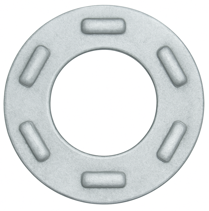
Load-Indicating Washer
A load-indicating washer is a special washer that tells you when a bolted joint has reached the required preload. The most common type is the direct-tension-indicator (DTI) used with structural bolts: one face of the washer has small compressible protrusions (“bumps”). As you tighten the joint, those bumps flatten in a controlled way; when they’re compressed to a specified gap, the bolt has achieved at least the minimum tension. Inspectors verify this by checking the remaining gap with a thin feeler gauge, or—on “squirter” DTIs—by looking for a ring of colored silicone that extrudes at the correct load.
DTIs move quality control from torque (which is affected by friction) to actual bolt tension at the joint. They’re widely used in steel construction and heavy fabrications to verify preload on high-strength bolts, and they complement other methods like calibrated wrench and turn-of-nut. They don’t keep a joint tight by themselves (they are not lock washers); they simply indicate that the required tension was achieved during installation.
Proper installation is essential. You select a washer matched to the bolt size/grade, seat the protrusions against a flat, hardened bearing surface—either under the bolt head or under a hardened flat washer beneath the nut, exactly as the manufacturer specifies—and tighten from snug to final tension until the gauge check passes or the silicone shows. After you first load the connection, you re-check and re-torque if required. DTIs are generally single-use items and are not meant for continuous load monitoring; if you need ongoing measurement, you’d use load-monitoring bolts or instrumented load washers instead.
Minimum Breaking Load (MBL)
Minimum Breaking Load (MBL) is the lowest load at which a product is expected to fail (break) when tested to the applicable standard, based on the manufacturer’s rating. It represents a strength threshold, not a recommended working load, and it is typically used as the basis for establishing the Working Load Limit (WLL) by applying a required design factor (for example, WLL = MBL ÷ design factor, when that approach is specified).
MBL is commonly stated for wire rope, chain, slings, synthetic rope, and rigging hardware, and it assumes proper configuration and test conditions. The actual breaking load in a specific test may be higher than the minimum value, but ratings and safety calculations are built around the minimum to ensure consistency. Because configuration and loading conditions matter, MBL can be reduced effectively by factors such as knots, sharp bends (D/d), termination efficiency, wear, corrosion, temperature, shock loading, side loading, or improper thread engagement—which is why WLL and application rules must be followed even if the published MBL looks high.
AKA: Minimum Breaking Strength (MBS), Breaking Load Limit (BLL)
Proof Load
Proof load is the maximum load that a fastener (such as a bolt, screw, or nut) can withstand without experiencing any permanent deformation. It represents the highest level of stress that can be applied to the fastener while ensuring that it remains within its elastic range—meaning it will return to its original dimensions once the load is removed. Beyond the proof load point, the material begins to deform plastically, leading to a permanent stretch or distortion that can compromise the fastener’s performance and integrity.
In practical terms, proof load serves as a safety benchmark used to verify that a fastener meets its specified strength requirements. During testing, the fastener is tightened or loaded up to its proof load (usually expressed as a specific percentage of its tensile strength, often around 85% to 95%) and then released. If it returns to its original shape and dimensions without yielding, it passes the proof test.

Proof load is usually specified in terms of force (N or lbf) or stress (MPa or ksi), depending on whether it’s defined for the entire fastener or for a particular cross-sectional area. The corresponding test ensures that the fastener can handle expected service loads without stretching, loosening, or losing clamping force.
For example, in high-strength steel bolts such as property class 8.8, the proof load is approximately 80% of the minimum tensile strength. This ensures that in normal service conditions, the bolt remains in the elastic range even when fully tightened, providing consistent and reliable clamping without risk of permanent deformation.
In summary, proof load defines the upper limit of safe, elastic loading for a fastener, ensuring it can perform reliably under tension without suffering permanent damage. It is a critical parameter in fastener design, testing, and quality assurance—helping engineers select the right fastener grade and tightening torque for each application.
Rated Load
Rated load is the maximum load an item is designed, built, and authorized to handle under specified conditions, as established by the manufacturer (or the governing design standard/code). In everyday plant language: it’s the “do not exceed” number on the nameplate—because above that point, you’re outside the verified safe operating envelope.
In lifting and material handling—cranes, hoists, slings, shackles, hooks, below-the-hook devices—rated load is tied to the weakest link in the load path and assumes specific conditions such as proper configuration, correct angle factors, approved attachments, intended orientation, and an acceptable duty/service classification. If any of those conditions change (for example, sling angle goes shallow, the load is side-pulled, the lift is shock-loaded, or the temperature is outside the rated range), the effective allowable load can drop sharply even though the nameplate number didn’t change.
Rated load is closely related to—but not the same as—breaking strength. Most lifting gear is built with a safety factor between ultimate failure and the rated number, but you should treat rated load as the only number that matters operationally. Exceeding it can cause permanent deformation, accelerated fatigue damage, loss of stability/control, or immediate failure—especially if dynamic effects (sudden starts/stops, snagging, impact) are present.
On equipment labels you’ll often see rated load expressed as WLL (Working Load Limit) or SWL (Safe Working Load), sometimes alongside other constraints like maximum reach, radius, line pull, duty class, or temperature limits. The main takeaway: rated load is not a suggestion—it’s the engineered limit for that tool in that specific setup.
Safe Working Load (SWL)
Safe Working Load (SWL) is the maximum load that a piece of equipment is permitted to support or lift in service under the conditions it was intended for. In plain shop terms: it’s the “this is the most you’re allowed to put on it” number—set so you have margin against failure, deformation, and fatigue.
In rigging and hoisting, SWL is meant to reflect real operating effects, not just a static hang test. OSHA describes SWL in the context of hoisting as being established with due consideration to static and dynamic loads on the hoist and supporting structure (so things like starts/stops and impact effects are part of the thinking).
You’ll also see SWL used as a marking requirement in some regulations—for example, OSHA’s longshoring/cargo-handling gear rule requires certain gear to have its safe working load plainly marked once it exceeds a threshold.
One practical caution: SWL is often treated as “older/legacy wording,” and modern standards and manufacturers more commonly use “WLL (Working Load Limit)” or “rated capacity/rated load.” In everyday use many people treat SWL and WLL as the same idea (a safe maximum), but SWL can get fuzzy if someone tries to “adjust” it for site conditions. The safest rule is: use the manufacturer’s marked rating (WLL/rated capacity), apply any required derating factors (angle, temperature, side-load, radius, duty), and never exceed the lowest rated item in the load path.
Shear Load
Shear load is a sideways force applied across a material, fastener, or joint that tries to make one part slide past another. In a fastened assembly, shear load acts perpendicular to the fastener’s axis, rather than pulling along the length of the bolt or screw.
A simple example is a bolt passing through two overlapping plates. If one plate is pushed to the left and the other is pushed to the right, the bolt is loaded in shear. The force is trying to cut across the bolt’s shank at the joint line, almost like scissors trying to slice through the fastener.

Shear load is different from tensile load. Tensile load pulls a fastener lengthwise and tries to stretch it. Shear load pushes sideways across the fastener and tries to slide or cut it. In many real assemblies, a fastener may experience both tension and shear at the same time, but the terms describe different directions of force.
In fastener applications, shear load is important for bolts, pins, rivets, screws, anchors, dowel pins, clevis pins, and structural connectors. Parts exposed to sliding, side loading, vibration, impact, or bracket-style loading often need to be checked for shear. If the shear load is too high, the fastener may bend, deform, fracture, tear through the material, or cause the hole in the joined part to elongate.
Shear load can occur in single shear or double shear. In single shear, the fastener is being sheared across one plane, such as two plates joined together. In double shear, the fastener is supported in a way that creates two shear planes, such as a clevis joint with a center plate captured between two outer plates. Double shear usually allows the load to be shared across two sections of the fastener instead of one.
In simple terms, shear load is the sideways “slide-apart” force on a joint. It asks the fastener, “Can you keep these parts from moving past each other without being cut, bent, or broken?”
Tensile Load
Tensile load is a pulling force applied along the length of a material, fastener, or assembly that tries to stretch it or pull it apart. In fastener terms, tensile load acts in the same general direction as the bolt or screw’s axis, placing the fastener in tension rather than shear, compression, or bending.
For example, when a bolt clamps two plates together, the bolt is stretched slightly as the nut is tightened. That stretch creates tension in the bolt, and the resulting clamping force holds the joint together. If an external force then tries to separate the plates, that force adds tensile load to the fastener. If the tensile load becomes too high, the fastener may permanently stretch, yield, neck down, fracture, or pull the threads out of the mating part.

Tensile load is different from tensile strength. Tensile load is the actual force being applied, usually measured in pounds-force, newtons, kilonewtons, or kips. Tensile strength is the material’s ability to resist that force before yielding or breaking, usually expressed as stress, such as psi, ksi, MPa, or N/mm².
In bolted joints, tensile load is closely related to preload or clamp load. Preload is the intentional tensile load created in a fastener during tightening. A properly tightened bolt behaves a little like a stretched spring: it pulls the joint members together and helps prevent loosening, joint separation, fatigue failure, and leakage in gasketed assemblies.
A simple way to picture it: if you pull on both ends of a bolt, rope, rod, or threaded stud, you are applying tensile load. The part is being asked, “How much pulling force can you take before you stretch too far or break?”
Ultimate Design Load
Ultimate design load is the maximum load a joint, fastener, anchor, or connection is required to resist at the “ultimate” (strength) limit state, after applying the applicable load factors to the expected service loads. In other words, it’s the factored demand used to check that the connection will not fail by yielding, fracture, pullout, shear, prying, tear-out, or other strength-controlled modes.
In practice, the ultimate design load is calculated from load combinations (dead load, live load, wind, seismic, pressure, etc.) using a design method such as LRFD/limit-state design, where service loads are multiplied by factors (e.g., 1.2D + 1.6L type combinations). That factored load is then compared against the connection’s factored resistance (capacity reduced by a resistance factor, or otherwise adjusted per the governing code/standard). The connection is acceptable when the available strength ≥ ultimate design load.
This is different from working load / allowable load, which is typically based on service-level loads and includes safety through safety factors rather than load factors. You’ll often see all three ideas in fastener/anchoring language: service load (working load) → ultimate design load (factored) → ultimate capacity/strength (tested or calculated failure load).
Working Load Limit (WLL)
Working Load Limit (WLL) is the maximum load that a lifting or rigging component is permitted to carry in normal service when it is used correctly and within its rated configuration. It is a rated, allowable load that already includes a margin of safety relative to the component’s minimum breaking strength, so it is not the load at which the item fails.
WLL is set by the manufacturer and is tied to specific conditions of use, such as the component size and grade, thread engagement, temperature limits, and the type of connection (e.g., straight lift vs. angled/sling loading). For many rigging products, the WLL is derived from the minimum breaking load divided by a design factor (often 4:1, 5:1, or higher depending on the product category and standard), and it may be reduced for non-ideal loading conditions like side loading, shock loading, or elevated temperature.
In industrial fastener contexts, you’ll see WLL on eyebolts, hoist rings, lifting lugs, lifting sockets/inserts, shackles, turnbuckles, and other rigging hardware. The WLL is the number you use for safe selection and planning; exceeding it can cause permanent deformation, loss of preload/fit, fatigue damage, or catastrophic failure—even if the component does not break immediately.