Learning Hub
Glossary
Washer
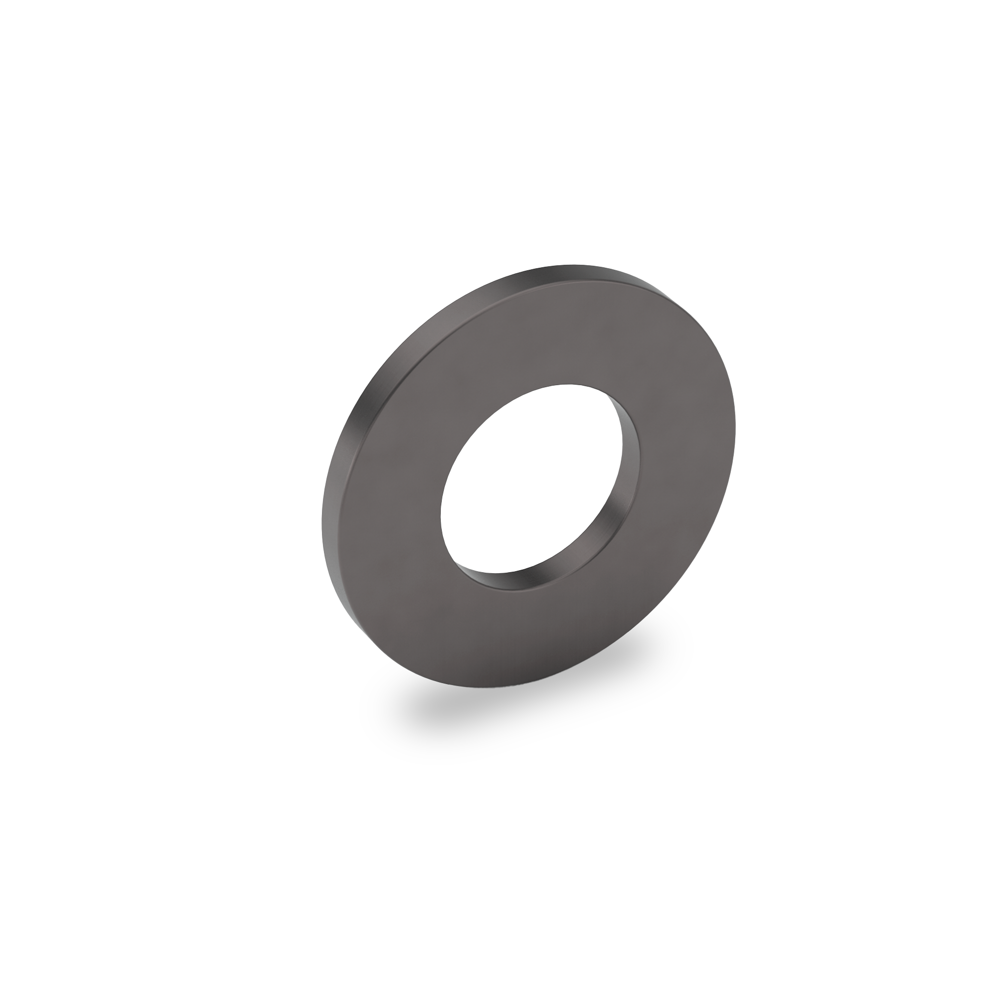
A washer is a thin, flat disc—usually made of metal, plastic, or rubber—used with a bolt, screw, or nut to distribute load, prevent damage, and improve the security of a fastened joint. Washers are among the simplest but most essential fastener components in mechanical assembly.
When a bolt or screw is tightened, a washer spreads the clamping force over a wider surface area, preventing the fastener head or nut from embedding into the material beneath. This is especially important when fastening into softer materials such as aluminum, wood, or plastic. Washers also help maintain even pressure, improve grip, and reduce loosening caused by vibration, movement, or thermal expansion.
There are several main types of washers, each with specific functions.
Flat washers are the most common type. They sit between the fastener head (or nut) and the surface, distributing load and protecting the material.
Spring washers (or lock washers) are designed to resist loosening by applying tension or friction against the fastener head, helping maintain clamping force under vibration. Common designs include split lock, tooth lock, and wave washers.
Fender washers have a larger outer diameter than standard flat washers, providing extra load distribution for thin or soft materials.
Sealing washers, made of rubber or metal-rubber combinations, create a liquid- or airtight seal, preventing leaks in plumbing, automotive, or electronic applications.
Washers can be made from steel, stainless steel, brass, copper, aluminum, nylon, or composite materials, depending on the environment and mechanical demands. Stainless steel and zinc-plated versions offer excellent corrosion resistance, while hardened steel types are used in structural and high-load assemblies.
Washer Face
The flat surface under the head of a bolt or screw that directly contacts the clamped material. This surface is often machined or chamfered to help distribute the clamping load evenly, reduce wear on the material, and prevent the fastener from embedding or sinking into the installation surface.
Waspaloy
Waspaloy is a nickel-based, age-hardenable superalloy identified as UNS N07001. It is used in demanding high-temperature applications where a material must retain strength, resist oxidation, and continue performing under heavy mechanical stress. Because of that combination of properties, Waspaloy is strongly associated with aerospace and gas-turbine service rather than ordinary commercial hardware.

Metallurgically, Waspaloy is designed to develop much of its strength through precipitation hardening, while its base chemistry also supports corrosion and oxidation resistance at elevated temperatures. Its composition is built primarily around nickel, chromium, cobalt, and molybdenum, with titanium and aluminum added to help form the strengthening phases that give the alloy its high-temperature capability. NIST reference data for UNS N07001 show a composition centered at roughly 58% nickel, 19% chromium, 12–13% cobalt, about 4% molybdenum, and about 3% titanium, with smaller additions of aluminum and other controlled elements.
In practical use, Waspaloy is best known for gas-turbine engine parts and other aerospace components exposed to heat and stress. It has long been used for parts such as turbine disks, shafts, seals, rings, casings, and fasteners, especially where ordinary stainless steels or lower-performance alloys would not hold strength well enough at elevated temperature. NASA technical literature specifically references Waspaloy in turbine-disk applications and also documents its use in aerospace fasteners and bolted flange assemblies.
From a fastener and materials standpoint, Waspaloy is important because it occupies a much more specialized category than common stainless steels such as 18-8 or 316. It is selected when the application requires a fastener or component to survive high load, high heat, and severe service conditions while maintaining structural reliability. That is why it appears in aerospace hardware and engine-related assemblies rather than in general industrial fastening applications.
Watt
A watt (symbol W) is the SI unit of power—the rate at which energy is transferred or work is done.
On one line: 1 W = 1 J/s (one joule per second).
In industrial electrical terms, wattage is how you express how fast equipment consumes or delivers energy. For DC (and simple resistive loads), power is P = V·I (watts = volts × amps). For AC, you’ll often care about real power as P = V·I·PF where PF is power factor, because motors and inductive loads draw current that doesn’t all turn into usable work.
In mechanical terms, watts connect directly to force and motion: P = F·v (power equals force times velocity) and for rotating equipment P = τ·ω (torque times angular speed). That’s why motor nameplates, VFD sizing, pump curves, heaters, and compressor loads are commonly expressed in watts or kilowatts—because it’s the “how hard/how fast” unit.
Wave Washer
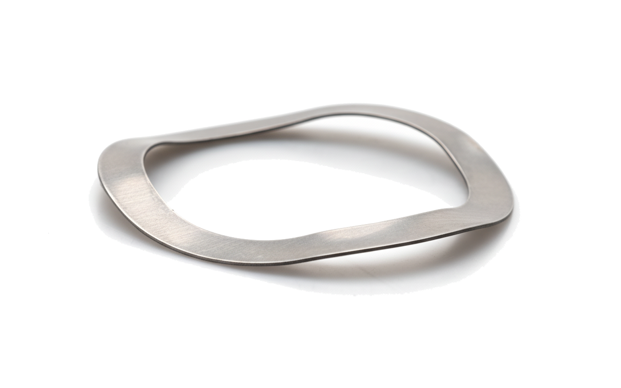
A wave washer, also known as a wave spring, is a unique type of washer characterized by its wavy or curved shape. Unlike a flat washer, it's designed to function as a spring, providing a continuous force within an assembly. This spring-like action allows it to absorb shock, reduce vibration, and compensate for small variations in component dimensions or thermal expansion. Wave washers are particularly useful in applications where axial space is limited, such as in bearing preloading or taking up slack in an assembly to maintain a tight fit.
When a wave washer is compressed between two components, its wavy form flattens slightly, generating an elastic force that pushes back on the parts. This continuous pressure helps prevent components from loosening due to vibration and ensures a constant load is applied. They are an excellent solution for tasks like cushioning light loads and maintaining a secure connection in various industries, including automotive, aerospace, and electronics.
Wedge Lock Washer
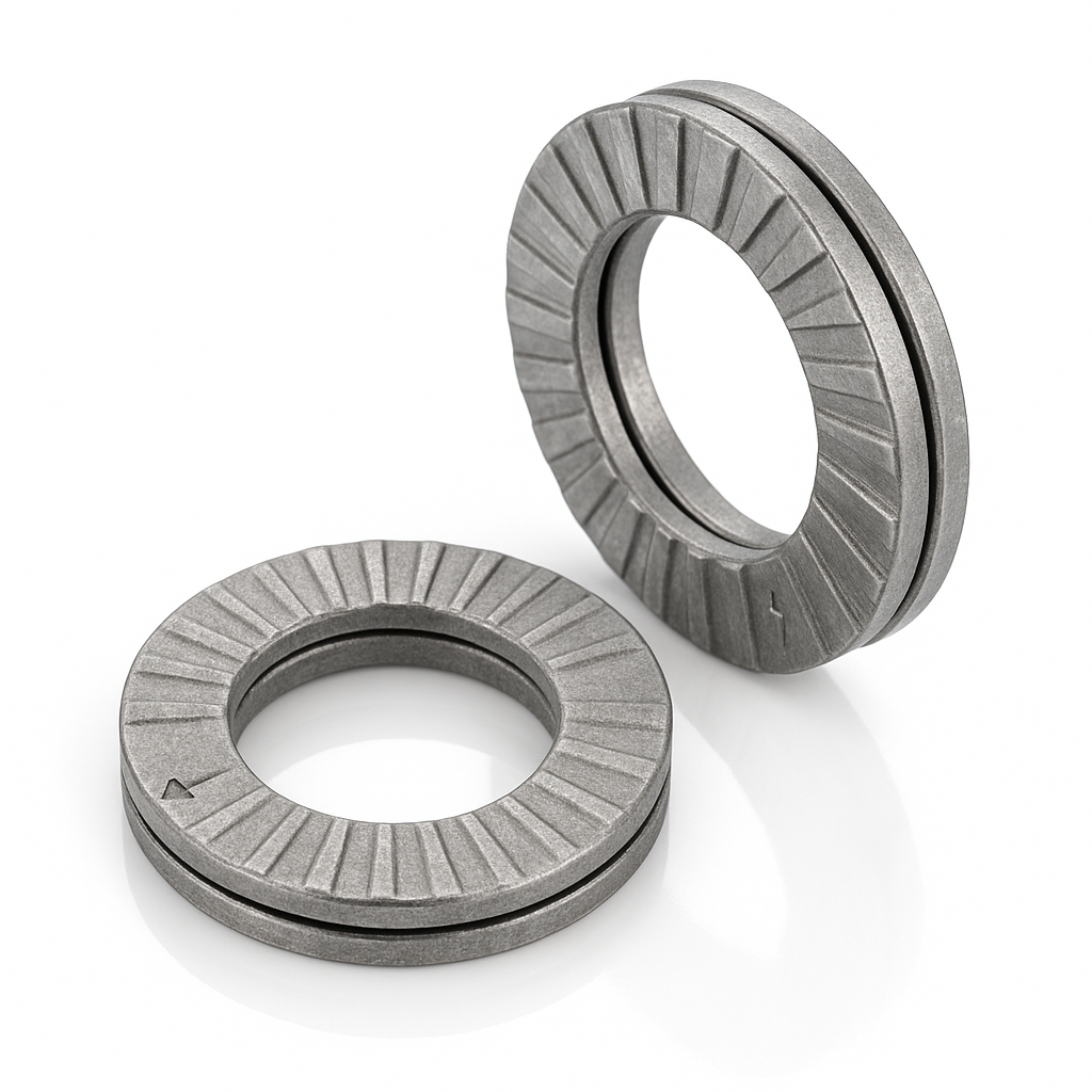
A wedge lock washer is a two-piece washer set designed to keep a bolted joint from loosening under vibration or dynamic loads. The washers are paired with cams on their mating faces and radial serrations on the outer faces. Installed cam-to-cam, the serrations bite into the nut/bolt head and the joint surface so nothing slips externally. If the bolt tries to rotate loose, the cams ride up each other; because the cam angle is greater than the thread pitch angle, the bolt must stretch to move—so preload increases and the joint resists loosening.
They’re reusable, work with lubricated or dry threads, and are common on machinery, vehicles, rail, and wind/energy equipment. For best results, use them as a pair only, cams facing each other, against hard, flat bearing surfaces (use a hard flat washer first on soft or painted materials). Variants exist for through holes and for countersunk screws.
Wedge Socket
A wedge socket is a mechanical wire-rope termination that forms an eye by looping the wire rope around a wedge inside a socket body. The rope is inserted through the socket, bent back to create a bight, and the wedge is driven into the socket so the rope is gripped by wedging action and friction under load. As the load increases, the wedge is pulled tighter, increasing the holding force. Wedge sockets are popular because they are quick to install, adjustable, and field-serviceable—the rope can often be removed and replaced without special pouring or swaging equipment.

Wedge sockets are widely used on crane hoist lines, winches, derricks, draglines, and heavy rigging where wire rope is regularly changed or where a termination needs to be installed on site. The design typically requires correct orientation: the live (loaded) end must be positioned as specified by the manufacturer, and the dead end is retained with a clip or tailing arrangement—improper installation can allow slippage or greatly reduce capacity.
Compared with poured (spelter) or swaged sockets, wedge sockets generally have lower termination efficiency and are more sensitive to installation details, rope construction, and loading conditions. Because of that, they must be selected and used according to the manufacturer’s ratings and the applicable rigging standards, including attention to minimum tail length, correct wedge/rope size match, and inspection for slippage, broken wires, deformation, or cracking.
Wedge Tensile Testing
Wedge tensile testing is a fastener test used to evaluate the tensile strength and head-to-shank integrity of a bolt or screw while it is being pulled at a slight angle. Instead of pulling the fastener perfectly straight, the test uses a wedge-shaped washer or fixture under the head so the fastener is forced to carry tensile load while also experiencing bending stress near the head.
The purpose is to prove that the fastener can withstand a specified tensile load without failing prematurely at a weak transition area, especially where the head joins the shank. That area is important because it often contains geometry changes, fillets, forging flow lines, and possible stress concentrations. A bolt might pass a straight tensile test but still reveal weakness when loaded through a wedge because the angled setup places extra demand on the head-to-body junction.

In a typical wedge tensile test, the fastener is installed through a hardened wedge fixture and threaded into a test nut or gripping fixture. A tensile testing machine then pulls the fastener along its axis until it reaches the required proof or tensile load, or until it fractures. The wedge under the head creates a controlled angular bearing condition, making the test more severe than a simple straight pull.
For externally threaded fasteners, wedge tensile testing is commonly used to confirm that the bolt or screw meets strength requirements and that the head does not pop off, crack, separate, or fail below the required load. If failure occurs, the location and mode of failure matter. A fracture through the threaded section may be acceptable in some test conditions, while failure at the head-to-shank junction may indicate a problem with material, heat treatment, forging quality, under-head radius, or overall fastener design.
Wedge tensile testing is especially relevant for hex bolts, structural bolts, cap screws, and other headed fasteners used in load-bearing applications. It helps verify that the fastener is not only strong in pure tension, but also robust when real-world loading is slightly misaligned. In the land of fasteners, loads are not always polite enough to pull perfectly straight.
In simple terms, wedge tensile testing is a controlled pull test with the fastener head tilted on a wedge. It asks: Can this bolt survive tensile loading even when the head is forced into a more demanding, angled condition?
Weld Nut
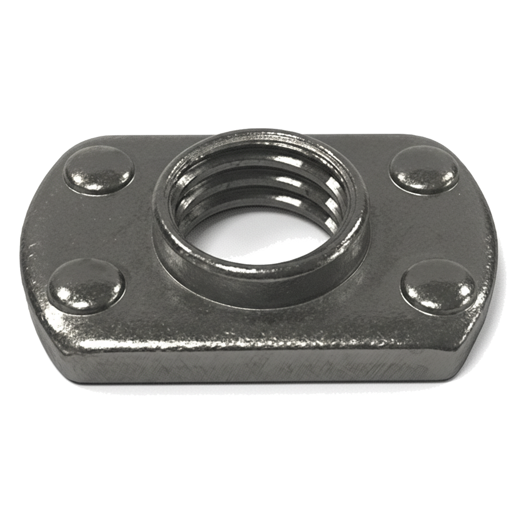
A weld nut is a specialized type of nut designed to be permanently attached to another metal object, most often a metal sheet or plate, by welding. Unlike standard nuts, weld nuts have unique features such as flanges, locating bosses, or welding projections (small, raised points) on one face. These projections are engineered to melt during the welding process, creating a strong, permanent bond between the nut and the base material.
The primary purpose of a weld nut is to create a secure, high-strength threaded connection point on a surface where a tapped hole would be impossible or impractical, such as on thin sheet metal. Once welded, the nut becomes an integral part of the assembly, providing excellent resistance to torque, vibration, and loosening. This makes them ideal for heavy-duty applications in industries like automotive manufacturing, construction, and furniture production. Weld nuts are a type of "captive nut," meaning they are permanently integrated into the component, simplifying assembly by allowing a bolt to be fastened from a single side without needing a wrench to hold the nut in place.
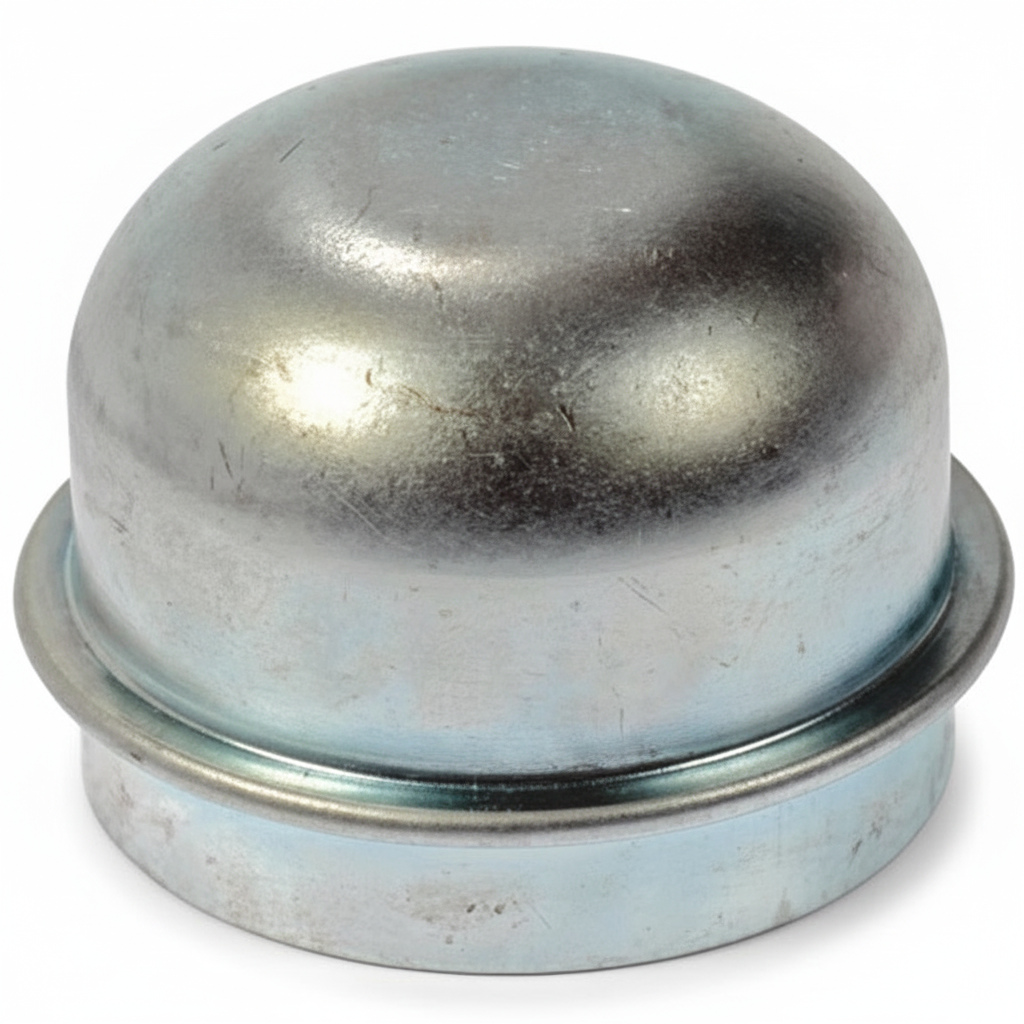
Wheel Bearing Dust Cap
A wheel bearing dust cap (also called a grease cap) is a protective metal or plastic cover that fits over the end of a wheel hub to seal and protect the wheel bearings from contaminants such as dust, dirt, water, and debris. Its main purpose is to keep the bearing grease clean and contained, ensuring smooth rotation and preventing premature wear or failure of the wheel bearings.
The dust cap is typically pressed or tapped into place on the hub’s bearing cavity. It forms a snug fit that shields the bearings from the outside environment while allowing for easy removal when servicing or re-greasing. Some dust caps include a rubber plug or access port for adding grease without removing the cap—common in trailer hubs and marine applications.
Most wheel bearing dust caps are made of stainless steel, zinc-plated steel, or durable plastic, chosen for corrosion resistance and longevity. They are widely used in automotive wheels, trailers, agricultural machinery, and industrial equipment where exposed rotating hubs are present.
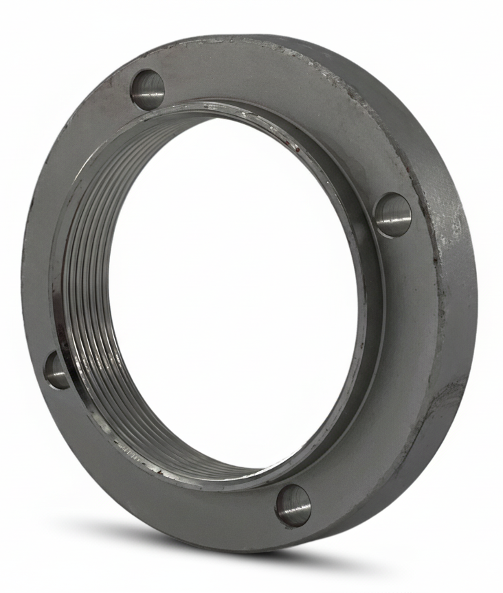
Wheel Bearing Retaining Nut
A wheel bearing retaining nut is a specialized fastener used to secure the wheel bearing assembly to a vehicle’s spindle or axle shaft. Its main role is to hold the wheel hub and bearing tightly in place, ensuring that the wheel rotates smoothly while maintaining proper alignment and preload on the bearing. Because wheel bearings are critical to both safety and performance, the retaining nut is designed to withstand constant rotational forces, vibration, and heavy loads.
These nuts are typically large, heavy-duty, and may feature special designs such as castellations (slots) or locking mechanisms. In many cases, they are used with a cotter pin, lock washer, or other locking device to prevent loosening during operation. Some modern applications use self-locking versions, which incorporate deformations or specialized threads to maintain torque without the need for additional hardware.
The function of the wheel bearing retaining nut goes beyond simply holding parts together. By properly tightening the nut to a specified torque (and sometimes with an additional angle of rotation), the bearing preload is controlled. This preload determines how tightly the rolling elements inside the bearing fit against their raceways, which affects both performance and service life. Too little preload can result in excessive play, vibration, and premature wear, while too much preload can cause overheating, high friction, and bearing failure.
Wheel bearing retaining nuts are found in automotive, truck, trailer, and heavy machinery applications. Their proper installation is crucial for safety, as a loose or improperly torqued nut can lead to catastrophic wheel detachment. Advantages of these nuts include reliable bearing retention, controlled preload, and enhanced safety. However, they often require precise torque specifications and sometimes special tools for installation and removal. Many are considered single-use fasteners, meaning they should be replaced whenever removed to ensure integrity.
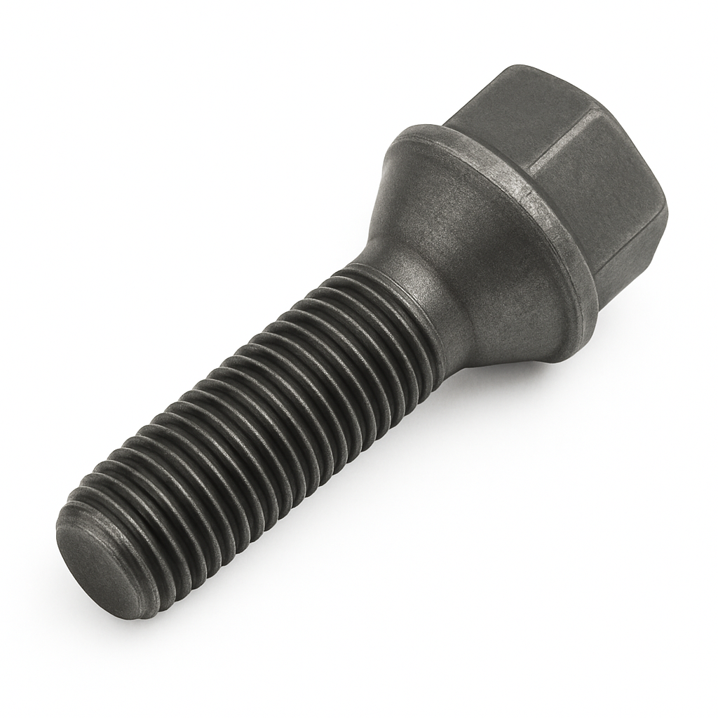
Wheel Bolt
A wheel bolt is a fastener used to secure a vehicle’s wheel directly to the hub or brake drum without the use of separate wheel studs. Instead of sliding the wheel over fixed studs and then tightening lug nuts, a wheel bolt passes through the wheel’s bolt hole and threads directly into the hub.
Wheel bolts are essentially a combined stud-and-nut system in one piece. They’re commonly used on many European vehicles (BMW, Audi, Mercedes-Benz, VW, etc.) where the hub is drilled and tapped with threaded holes. The design allows for a clean mounting surface, but installing wheels can be trickier since the wheel must be held in place while bolts are threaded in.
You’ll find wheel bolts on a wide range of passenger vehicles, especially in Europe. They come in various lengths, diameters, and seat types (cone seat, ball seat, flat seat) to match the wheel design and ensure proper load distribution. Longer wheel bolts are often used when installing aftermarket wheels or wheel spacers.
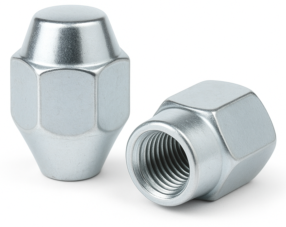
Wheel Nut
A wheel nut—commonly called a lug nut—is the fastener that clamps a vehicle’s wheel to the hub by threading onto wheel studs. Most are hex nuts designed to be tightened with a wrench, and the nut’s seating shape mates with the wheel to center it and hold the clamping force that keeps the wheel secure under load and vibration.
Common seat types are conical/tapered (often 60°), ball/spherical, and flat or “mag/mag-washer”; nuts may be open- or closed-end, spline-drive, or locking (anti-theft). For safety, use the exact seat style and thread specified, tighten with a torque wrench in a star pattern to the manufacturer’s torque, and avoid lubricants unless specified. (Not to be confused with lug bolts, where a bolt threads into the hub instead of a nut onto a stud.)
AKA: Lug Nut
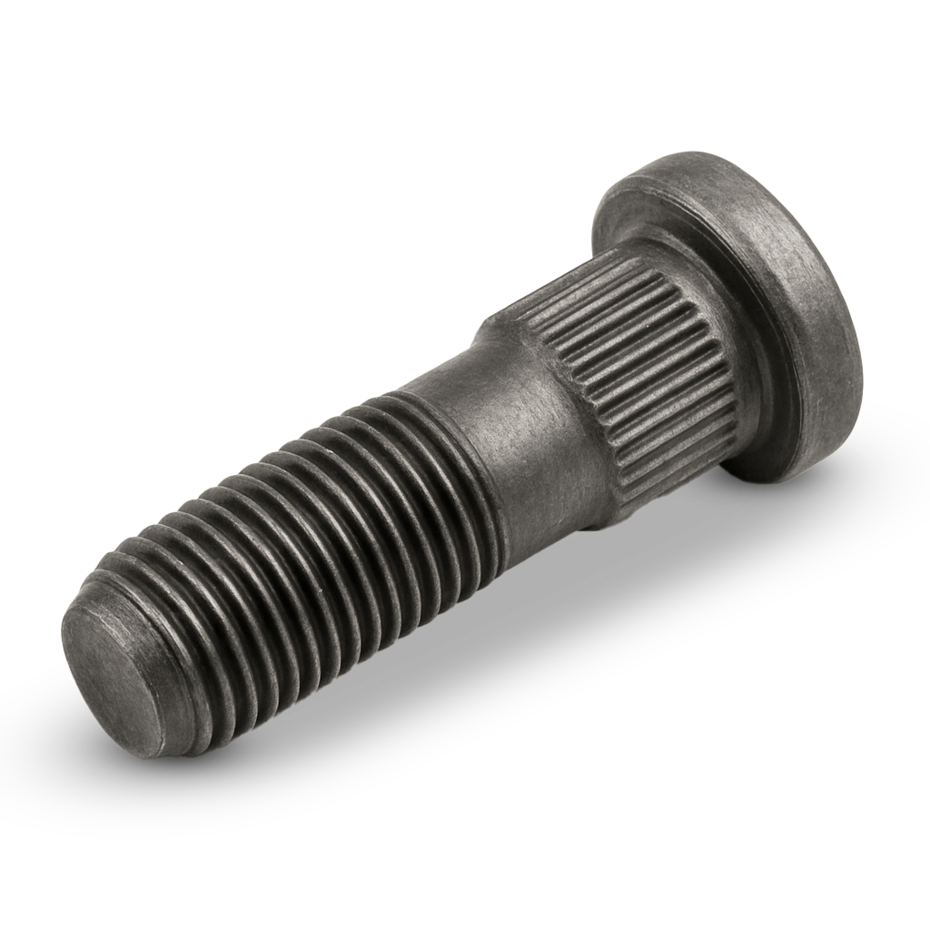
Wheel Stud
A wheel stud is a threaded fastener that’s permanently mounted in a vehicle’s wheel hub or brake drum. It serves as the anchor point for the wheel, allowing a lug nut to thread onto it and secure the wheel to the vehicle.
Unlike a lug bolt (which combines the stud and nut into one piece), a wheel stud stays fixed in the hub. This setup makes mounting wheels easier: you simply slide the wheel over the studs and then fasten it with lug nuts. Studs are typically made from hardened steel to handle the high clamping forces and stresses from braking, acceleration, and cornering.
Wheel studs are standard on most cars, trucks, and commercial vehicles. They come in different diameters, lengths, and thread pitches depending on the vehicle’s design and are often replaced when damaged, stretched, or when longer studs are needed for aftermarket wheels or spacers.
White Rust
A chalky, white corrosion that forms on fasteners with zinc or cadmium-based metallic finishes, such as electroplated zinc or zinc-rich coatings. White rust indicates the surface finish has started to degrade, usually due to moisture or improper storage. This residue flakes off over time, exposing the underlying steel.
Width Across The Flats (WAF)
Width Across the Flats (WAF) refers to the distance measured between two opposite flat sides of a fastener’s head—typically a bolt, nut, or screw with a hexagonal or square shape. It defines the size of the wrench or socket needed to grip and turn the fastener properly.

For example, a standard hex bolt may have a WAF of 13 mm, meaning a 13 mm wrench fits snugly between the two opposite flats of the bolt head. This measurement ensures a secure fit for applying torque without slipping or rounding off the corners.
In engineering and manufacturing, WAF is a critical specification because it determines tool compatibility, torque application, and clearance space in assemblies. It is standardized under various systems such as ISO, DIN, ANSI, and SAE, with metric and imperial equivalents.
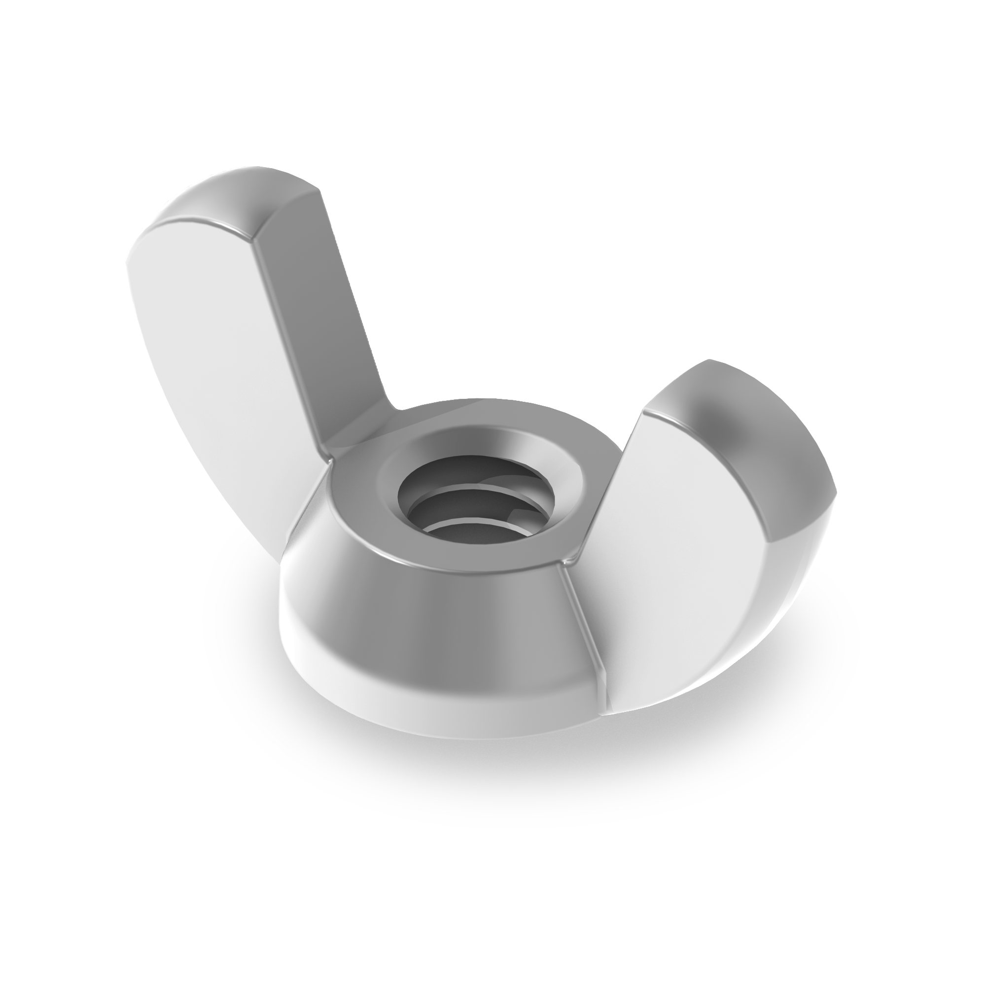
Wing Nut
A wing nut is a type of nut with two large metal “wings” projecting from its sides, allowing it to be easily tightened or loosened by hand without the need for tools. The wings provide extra grip and leverage, making it ideal for applications that require frequent assembly and disassembly or quick adjustments.
Structurally, a wing nut has a threaded central hole—just like a standard hex nut—that mates with a bolt, screw, or threaded rod. The “wings” extend outward from the nut’s body and are usually flat, curved, or slightly angled, giving the user a comfortable surface to twist with their fingers.
Wing nuts are commonly made from steel, stainless steel, brass, or aluminum, though they also come in nylon or plastic for lightweight or non-conductive applications. Metal versions may be zinc-plated or nickel-plated for corrosion resistance.
They are widely used in furniture assembly, equipment covers, clamps, light fixtures, musical instruments, and automotive parts—anywhere a part needs to be securely fastened yet easily removable. For example, they’re often found on tripod mounts, drum hardware, battery compartments, and machinery panels.
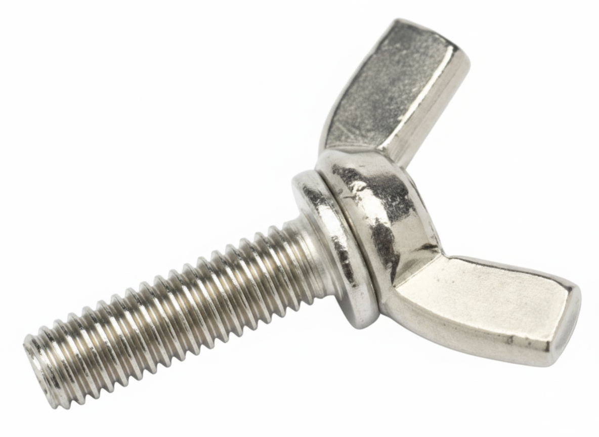
Wing-Head Thumb Screw
A wing-head thumb screw is a hand-operated machine screw whose head has two lateral “wings” so you can pinch and turn it with your thumb and forefinger. It’s a subtype of thumb screw designed for tool-free tightening and release, used anywhere frequent access or adjustment is needed—panels, guards, fixtures, electronics covers, and consumer products. Compared with knurled-head thumb screws, the wing shape gives greater leverage for higher hand-applied torque, which speeds assembly and removal without tools.
Most wing-head thumb screws use standard machine threads (metric and inch) and are installed into a tapped hole or used with a mating nut; length is typically measured from under the head to the end of the threads. Common materials include zinc-plated steel, stainless steel (A2/A4), brass, and engineering plastics like nylon for light-duty, non-marring applications; cast versions exist as well for certain hardware lines. Variants span stamped-wing steel styles, cast “American form” heads based on DIN patterns, and molded plastic heads, giving a range of strength, corrosion resistance, and feel in use.
There are established dimensional/selection standards: in inch series, ASME B18.6.8 covers thumb screws and wing screws; in metric, DIN 316 is widely used by manufacturers and distributors for wing screws. These standards help define head proportions, wing span, and thread ranges so parts interchange across suppliers.
In practice, wing-head thumb screws are meant for hand tightening and not for high-preload or vibration-critical joints. For better retention in service, users often pair them with washers, locknuts, or thread-locking features when appropriate, and choose materials/finishes that match the environment—for example, stainless in wet/food service, plated steel for general machinery, or nylon where a softer touch is needed. Typical catalogs group them alongside other thumb/wing hardware for quick, tool-free fastening.
Wire Forming
Wire forming is a manufacturing process that bends, cuts, coils, shapes, or otherwise forms metal wire into a specific finished part or component. Instead of starting with flat sheet, bar stock, casting, or machined billet, wire forming starts with round, square, rectangular, or specially shaped wire and uses mechanical force to create the required geometry. The process can produce simple bends, loops, hooks, clips, rings, pins, springs, handles, retainers, latches, guards, brackets, and many other industrial parts.
Wire forming is commonly done with CNC wire forming machines, slide-forming equipment, press brakes, fourslide machines, coiling machines, stamping presses, or custom tooling. The wire is usually fed from a coil or cut length, straightened, then bent or shaped through a sequence of controlled movements. Depending on the part, the wire may also be cut, chamfered, threaded, welded, flattened, pierced, swaged, heat treated, plated, passivated, or coated after forming.

In fastener and industrial hardware applications, wire forming is used to make parts that hold, retain, connect, support, latch, spring, or guide other components. Common examples include cotter pins, hitch pin clips, retaining clips, safety clips, wire lock pins, spring clips, snap rings, hose clamp wire forms, wire handles, hooks, eyelets, hanger parts, formed brackets, and custom retaining devices. These parts often function as simple but important fastening or retention components, especially where a bolt, nut, screw, or washer would be too rigid, bulky, expensive, or difficult to install.
The material used for wire forming depends on the application. Carbon steel is common for general-purpose formed parts, stainless steel is used where corrosion resistance is needed, spring steel is used where the part must flex and return to shape, and copper alloys may be used where conductivity, corrosion resistance, or non-sparking properties are important. Wire diameter, tensile strength, bend radius, springback, ductility, surface finish, and coating requirements all affect how successfully the wire can be formed.
Wire forming is valuable because it can produce strong, repeatable, lightweight components with relatively efficient material usage. For high-volume parts, it can be very cost-effective because wire can be fed continuously from coil stock and formed quickly. For custom or specialty applications, CNC wire forming also allows unusual shapes to be produced without the same level of tooling investment required for some stamped or machined components.
Wire Rope Clip
A wire rope clip is a clamp used to make a field-installed eye or lap splice in wire rope by clamping the rope’s “live” end to its “dead” (tail) end. The common U-bolt style has three parts: a U-shaped bolt, a grooved saddle that matches the rope contour, and two nuts. When tightened, the saddle and U-bolt compress the two rope legs together to hold the eye around a thimble or to secure a back-wrapped tail. There’s also a double-saddle “fist-grip” style that uses two opposed saddles and hex bolts instead of a U-bolt. Clips are made in galvanized forged steel for heavy duty and stainless for corrosion resistance; light-duty “malleable iron” versions exist but are not for critical or overhead lifting. Sizes are specified by rope diameter.

Correct installation is crucial because clips reduce rope strength and can slip if misapplied. For U-bolt clips, remember the rigger’s rule “never saddle a dead horse”: the saddle goes on the live end of the rope and the U-bolt bears on the dead end. Use the manufacturer’s table for your rope diameter to determine the number of clips (typically two to seven, increasing with size), the spacing between them (commonly a multiple of rope diameter), the required turnback length (the tail length from the eye before the first clip), and the nut torque. After fitting the thimble and placing the clips in order from the eye outward, tighten the nuts to the specified torque, load the assembly to the expected working load to seat wires, then re-torque. Re-check after the first period of service and as part of routine inspections. With double-saddle/fist-grip clips, orientation is symmetric (no mnemonic), but spacing, quantity, and torque tables still apply.
Even when installed perfectly, a clip termination usually achieves less than full rope efficiency (often on the order of ~80–90% at best, depending on clip style, rope construction, and compliance with torque/spacing). For critical, permanent, or high-efficiency terminations, use swaged sleeves, spelter or swage sockets, wedge sockets, or factory-made slings. Do not install clips over plastic jackets (strip the jacket in the clamped zone), avoid using them on rotation-resistant ropes unless allowed by the rope maker, and keep clips off kinks, crushed sections, or distorted strands. Inspect regularly for nut loosening, clip or saddle deformation, wire crushing, corrosion, or any sign of rope slippage, and replace components that show damage.
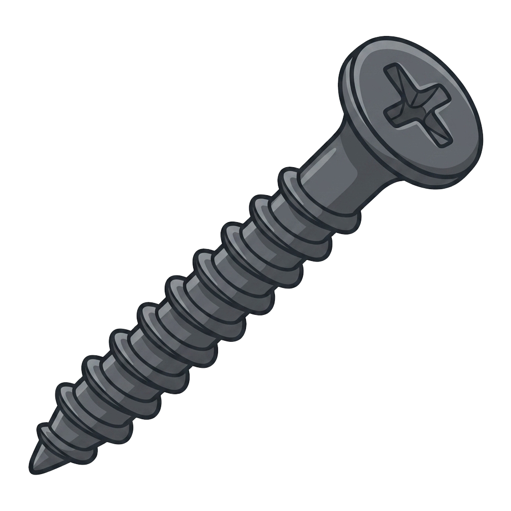
Wood Screw
Wood screws are a threaded fastener designed to join wood to wood, wood to hardware, or wood to another material by cutting and holding into the wood fibers as it is driven. Unlike a machine screw, which is intended to thread into a tapped hole or a nut, a wood screw forms its holding power directly in the wood. Its threads bite into the material, create resistance against pullout, and draw the joined pieces together.
A traditional wood screw has a tapered body, a sharp point, and relatively coarse threads. The sharp point helps the screw start in the wood, while the coarse threads provide strong grip in softer, fibrous material. Many wood screws are only partially threaded, with a smooth shank beneath the head. That unthreaded shank allows the top piece of wood to be pulled tightly against the lower piece instead of being held apart by threads in both pieces.
Wood screws are commonly available with several head styles, including flat head, oval head, round head, pan head, and hex washer head designs. A flat head wood screw is often used when the screw needs to sit flush with or below the surface of the wood, usually in a countersunk hole. A round or pan head may be used when the head can remain visible or when attaching brackets, hinges, plates, or other hardware.
The drive style can also vary. Older wood screws often used slotted drives, while modern versions commonly use Phillips, square, Torx/star, or combination drives for better torque transfer and less cam-out. Materials and finishes include plain steel, zinc-plated steel, stainless steel, brass, bronze, black oxide, phosphate, ceramic-coated, and other corrosion-resistant coatings depending on whether the screw is used indoors, outdoors, in treated lumber, or in marine environments.
In fastener selection, wood screws are chosen based on length, diameter or gauge, head style, drive type, thread design, material, finish, and the type of wood being fastened. Hardwoods often require a pilot hole to prevent splitting and reduce driving torque. Softwoods may accept the screw more easily, but pilot holes can still improve alignment and reduce the chance of damaging the wood. For exterior or pressure-treated lumber, corrosion-resistant screws are important because moisture and wood-treatment chemicals can attack ordinary steel.
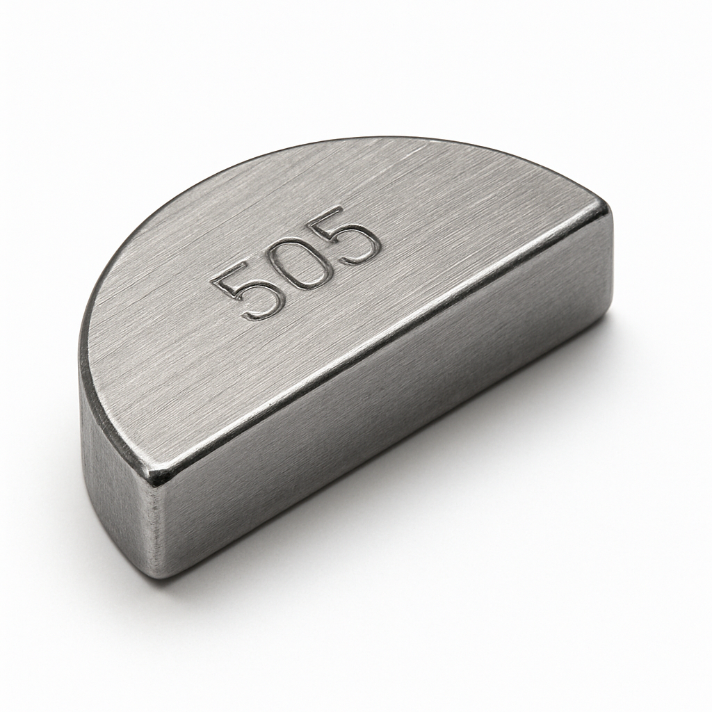
Woodruff Key
A Woodruff key is a small, semicircular (half-moon) machine key used to lock a rotating hub (gear, pulley, flywheel, etc.) to a shaft so they turn together. A matching Woodruff keyseat is milled as a circular pocket in the shaft; the flat top of the key projects above the shaft and fits into the keyway in the hub.
Because the key seats deeply in the shaft and presents a curved face, it self-aligns—especially helpful on tapered shafts—and is less likely to roll out during assembly. It also tolerates small axial or angular mismatches between hub and shaft better than a straight (rectangular) key. Typical materials are hardened carbon steel or stainless.
Trade-offs: the deep pocket weakens the shaft more than a shallow straight keyseat of the same width, so designers balance ease of assembly and alignment against shaft strength. Common failure modes are key shear and fretting if fits are loose or torque is excessive.
You’ll see Woodruff keys widely in automotive crankshafts and small-engine flywheels, machine tool spindles, alternators, and pumps. Sizes are standardized (inch: ANSI B17.6; metric: DIN 6888), selected by shaft diameter and hub keyway width.
Installation tips: press or tap the key into the shaft seat so its top sits slightly proud (typically ~25–35% of the key height above the shaft OD), align the hub keyway, and slide/press the hub on. Ensure snug fits and clean, burr-free seats to prevent wobble and wear.
AKA: Quadrant Key
Work Hardening
Work hardening (also called strain hardening) is the strengthening of a metal that occurs when it is plastically deformed, typically by cold-working operations such as cold heading, thread rolling, drawing, bending, stamping, or swaging. As the metal is forced to deform beyond its elastic limit, the density of dislocations in its crystal structure increases and they begin to tangle and obstruct each other, making further plastic deformation more difficult. The practical result is that the material becomes harder and stronger, while generally becoming less ductile.

Work hardening is a major factor in fastener manufacturing and performance. Cold-formed fasteners often gain strength from the forming itself, and thread rolling in particular can produce a stronger thread form than cut threads because it both work hardens the surface and preserves favorable grain flow. The tradeoff is reduced formability as work hardening accumulates; if too much cold work is introduced, parts can crack during forming or in service, so manufacturers may use intermediate annealing to restore ductility for additional forming steps. Work hardening can also affect installation and service behavior by increasing the likelihood of galling (especially in stainless steels) and by changing how the material responds under cyclic loading.
AKA: Strain Hardening
Working Load Limit (WLL)
Working Load Limit (WLL) is the maximum load that a lifting or rigging component is permitted to carry in normal service when it is used correctly and within its rated configuration. It is a rated, allowable load that already includes a margin of safety relative to the component’s minimum breaking strength, so it is not the load at which the item fails.
WLL is set by the manufacturer and is tied to specific conditions of use, such as the component size and grade, thread engagement, temperature limits, and the type of connection (e.g., straight lift vs. angled/sling loading). For many rigging products, the WLL is derived from the minimum breaking load divided by a design factor (often 4:1, 5:1, or higher depending on the product category and standard), and it may be reduced for non-ideal loading conditions like side loading, shock loading, or elevated temperature.
In industrial fastener contexts, you’ll see WLL on eyebolts, hoist rings, lifting lugs, lifting sockets/inserts, shackles, turnbuckles, and other rigging hardware. The WLL is the number you use for safe selection and planning; exceeding it can cause permanent deformation, loss of preload/fit, fatigue damage, or catastrophic failure—even if the component does not break immediately.
Wrought Alloy
A wrought alloy is a metal alloy designed to be mechanically worked into shape after it is cast into an initial form such as an ingot, billet, slab, rod, or bar. “Wrought” means the material has been worked by processes such as rolling, forging, extrusion, drawing, swaging, or cold forming, rather than being poured directly into a final mold shape like a casting.
The key idea is that a wrought alloy is not defined only by its chemistry, but also by how it is processed. After the alloy is melted and solidified into a basic starting shape, it is plastically deformed into a finished or semi-finished product. That deformation changes the internal grain structure of the metal, often improving strength, toughness, ductility, fatigue resistance, and consistency compared with many cast forms.
Common wrought product forms include sheet, plate, bar, rod, wire, tube, strip, extrusions, forgings, and cold-headed fastener blanks. In fastener manufacturing, many bolts, screws, pins, rivets, washers, and specialty parts begin as wrought wire, rod, or bar stock. The material may then be cold headed, hot forged, roll threaded, machined, heat treated, coated, or otherwise finished.
Wrought alloys are commonly contrasted with cast alloys. A cast alloy is formulated to flow well as molten metal and fill a mold. A wrought alloy is formulated to survive mechanical deformation without cracking. Because of that, wrought alloys generally need good ductility and controlled composition so they can be rolled, drawn, forged, or formed reliably.
For example, in aluminum metallurgy, alloys such as 6061, 7075, 2024, and 5052 are wrought aluminum alloys. They are typically rolled, extruded, or forged into usable shapes. Cast aluminum alloys, by contrast, include materials designed for foundry processes and die casting. Similarly, many steels, stainless steels, titanium alloys, nickel alloys, copper alloys, and aluminum alloys used in industrial components are supplied in wrought form.