Learning Hub
Glossary
K-Factor
K-factor is a sheet metal bending value that describes where the neutral axis sits within the thickness of the material during a bend. The neutral axis is the imaginary layer inside the metal that does not stretch or compress during forming. Material on the outside of the bend stretches, material on the inside of the bend compresses, and the neutral axis is the transition zone between those two conditions.
In press brake forming, K-factor is used to calculate bend allowance, which helps determine the correct flat blank size before the part is bent. Without it, a formed bracket, clip, cover, channel, or sheet metal component may come out too long or too short after bending.

The basic formula is:
K-factor = distance from inside surface to neutral axis ÷ material thickness
For example, if the neutral axis is located 0.040 inches from the inside surface of a 0.100-inch-thick sheet, the K-factor is 0.040 ÷ 0.100 = 0.40.
A K-factor is usually between 0.30 and 0.50 for most common sheet metal bending work. A value closer to 0.50 means the neutral axis is near the center of the material thickness. A lower value means the neutral axis has shifted closer to the inside of the bend. In real bending, the neutral axis usually shifts inward because the outside of the bend stretches more than the inside compresses.
K-factor is affected by material type, thickness, hardness, grain direction, inside bend radius, bend angle, tooling, and forming method. Softer materials, larger bend radii, and different forming processes can change how the material stretches and where the neutral axis ends up.
In manufacturing terms, K-factor is a practical correction factor. It helps convert a bent part into an accurate flat pattern. That matters when making formed metal parts such as brackets, guards, clips, panels, enclosures, channels, and custom fastener-related components where final dimensions need to match the print after bending.
Kammprofile Gasket
A kammprofile gasket (also spelled camprofile gasket) is a metal-core, serrated gasket designed for high-performance sealing in bolted flange joints. It consists of a machined metal ring (commonly stainless steel or other alloy) with concentric grooves/serrations on one or both faces, typically covered with a thin soft facing layer such as graphite or PTFE. When the joint is tightened, the soft facing conforms to flange surface imperfections while the serrated metal core concentrates compressive stress into the grooves, producing a tight, stable seal.

Kammprofile gaskets are used where you need reliable sealing under high pressure and/or temperature, thermal cycling, and vibration—common in refineries, chemical processing, power generation, and heat exchangers. Compared with many soft gaskets, they offer better blowout resistance and more consistent sealing with less sensitivity to minor flange surface damage. Compared with spiral wound gaskets, they often provide stronger recovery and stability during cycling and can be a preferred choice for heat exchanger pass partitions and other demanding flange geometries.
A key advantage is that the metal core is typically reusable if it isn’t damaged; in many cases the facing can be replaced rather than scrapping the entire gasket. Selection is usually based on the core material (matched to corrosion/temperature), facing material (graphite for high temperature, PTFE for chemical resistance), and the gasket style (ring type, heat-exchanger configurations, inner/outer guides as applicable). Proper performance still depends on achieving the required gasket seating stress with correct bolt load, flange finish, and tightening procedure—over-compression can damage facings, while under-load can lead to leakage, especially in cycling service.
AKA: Camprofile Gasket
Kelvin
Kelvin (symbol: K) is the SI base unit of thermodynamic temperature, meaning it’s the “official” unit used in science and engineering to measure temperature on an absolute scale. Unlike Celsius and Fahrenheit, Kelvin does not use a degree sign (it’s K, not °K), and it starts at absolute zero—the theoretical lower limit of temperature where thermal motion is minimized.
A key point is that Kelvin and Celsius have the same size increment: a change of 1 K is the same temperature change as 1 °C. What’s different is the zero point. The Kelvin scale is offset so that 0 K = −273.15 °C, which is why the conversion is K = °C + 273.15 (and °C = K − 273.15). For example, 25 °C = 298.15 K. Because Kelvin is absolute, temperatures in Kelvin are (in normal engineering contexts) non-negative, and that makes it the correct input for many physical equations.

Kelvin is the temperature unit used in a huge number of industrial and chemical calculations because many laws are derived for absolute temperature. Examples include the ideal gas law (PV = nRT), where T must be in Kelvin, and kinetics/thermodynamics relationships such as the Arrhenius equation (reaction rates vs. temperature), equilibrium constants, and properties that depend on absolute temperature (gas density, vapor pressure models, heat-transfer correlations, etc.). Using Celsius directly in these equations can produce nonsense results because Celsius is not absolute.
From a standards standpoint, the kelvin is part of the SI system maintained by international metrology bodies, and modern SI ties temperature measurement to fundamental constants (in practice, temperature is traceable through defined reference methods and calibrations). In real-world labs and plants, you’ll often see Kelvin used alongside standardized temperature scales and calibration practices so instruments (RTDs, thermocouples, IR sensors) can be validated and kept consistent.
Historically and naming-wise, the unit is named after Lord Kelvin (William Thomson), who helped formalize the concept of an absolute temperature scale. In short: Kelvin is “temperature with a true zero,” which is why it’s the default temperature unit for serious engineering, materials, and chemical work.
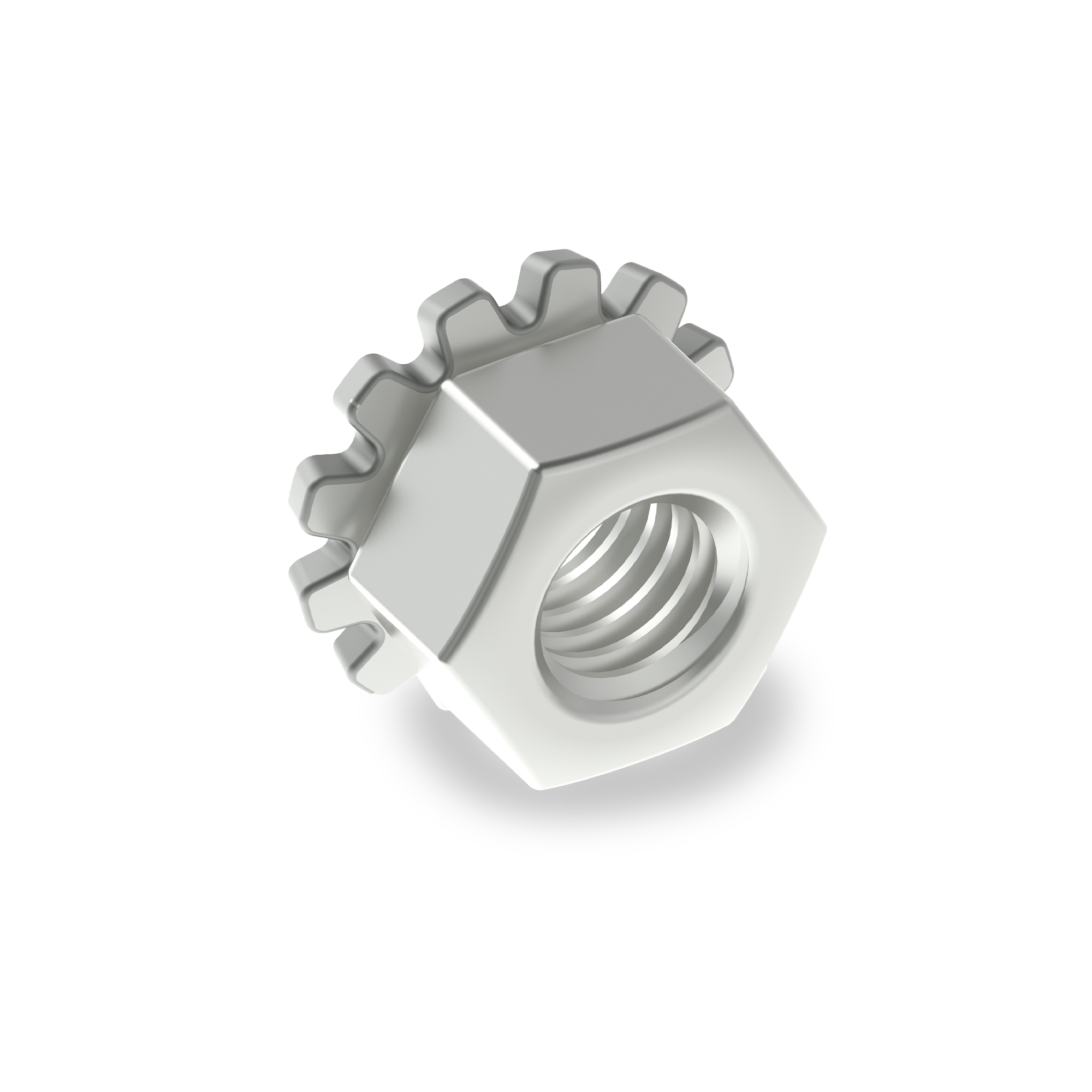
Keps Lock Nut
Keps Lock Nuts feature a free-spinning nut and an integrated external tooth washer designed to prevent loosening caused by vibration. When tightened onto a bolt, screw, or stud, the teeth of the free-spinning washer will grip the installation surface, creating resistance against rotation. The added friction helps maintain a secure bond, making this fastener suitable for applications where vibration and movement are concerns, such as in light-duty automotive and machinery assemblies.
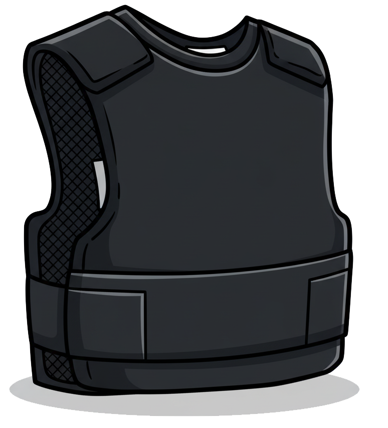
Kevlar
Kevlar is a high-strength synthetic fiber known for its exceptional toughness, heat resistance, and lightweight properties. It’s part of the aramid (aromatic polyamide) family of polymers and was developed by DuPont in 1965. Chemically, Kevlar is composed of long chains of para-aramid molecules that align parallel to one another and are held together by strong hydrogen bonds, giving the fiber remarkable tensile strength relative to its weight.
Kevlar is most famous for its use in bulletproof vests and body armor, but it’s also widely used in industrial and engineering applications, including fasteners, cables, hoses, belts, composite reinforcements, and FRP (fiber-reinforced plastic) materials. In fastener and structural applications, Kevlar fibers are sometimes woven into Kevlar-reinforced polymers, where they increase impact resistance and durability without adding significant weight.
Physically, Kevlar is five times stronger than steel by weight, yet it’s light and flexible. It also has excellent thermal stability—it doesn’t melt and can withstand temperatures up to about 450°C (850°F) before decomposing. Additionally, it’s resistant to abrasion, fatigue, and many chemicals, though it can degrade under prolonged UV exposure.
There are several types of Kevlar, including Kevlar 29 (used in ballistic and industrial applications) and Kevlar 49 (used in composites for aerospace and automotive structures).
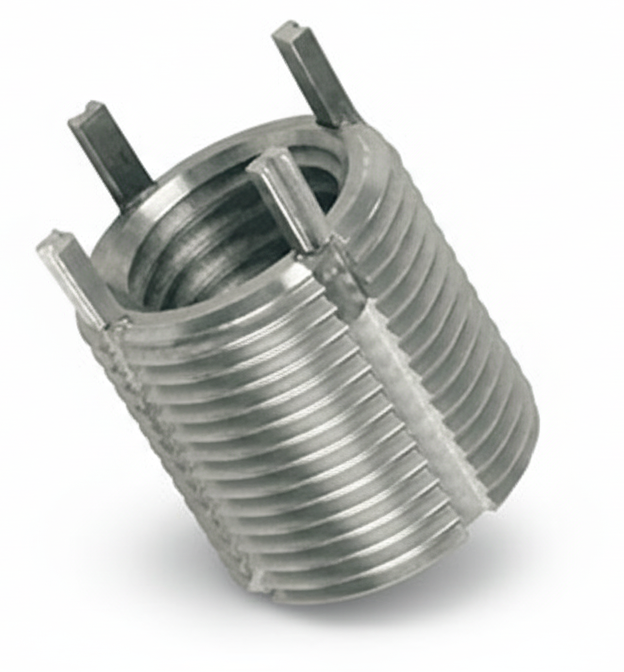
Key Locking Insert
A Key Locking Insert (often called a Keensert®) is a solid, threaded bushing used to create strong, wear-resistant internal threads in a parent material or to repair damaged threads. Unlike wire inserts, it has one-piece steel walls and mechanical locking keys that are driven into the parent material to prevent the insert from turning or pulling out under load and vibration.
How it works: the hole is drilled (or cleaned up) and tapped to the insert’s external thread size per the insert specification. The insert is screwed in until seated, then the pre-assembled keys are driven through notches at the top so they bite into the parent material, positively locking the insert. The result is a permanent internal thread—usually standard UNC/UNF or metric—ready for the service bolt or stud.
Where it’s used: high-vibration environments (aerospace, defense, heavy equipment); soft or thin materials such as aluminum, magnesium, and some castings that need stronger threads; and field repairs of stripped or oversized holes.
Types & options: available in free-running (standard internal thread) or self-locking (prevailing-torque) versions; in miniature/thin-wall and heavy-duty styles to suit space and load needs; and typically made of stainless or alloy steel with finishes/coatings for corrosion or galling control.
Advantages vs. wire inserts: higher pull-out and torque resistance, excellent anti-rotation thanks to the keys, and robust one-piece walls. Trade-offs: they require a larger tapped hole and add some weight and cost.
Keyway
A keyway is the machined slot used with a key to lock a hub (gear, pulley, coupling) to a shaft so they rotate together and transmit torque. In strict terms, the slot in the shaft is the keyseat and the slot in the hub is the keyway, but in industry “keyway” is often used for either. A rectangular or half-moon key fits between the two slots; torque is carried by the side faces of the key.
Good practice is to have a small top clearance between the key and the top of at least one slot so load stays on the sides, plus a little end clearance so thermal growth doesn’t jam the key. Because a slot cuts into the shaft, keyways reduce shaft strength locally; placing them away from the plane of maximum bending and using generous end radii (or Woodruff keys) helps curb stress concentrations and fretting.

Common styles include parallel (square/rectangular) keys for fixed hubs, Woodruff (half-moon) keys that self-align and are gentle on the shaft fillet, taper/gib-head keys that wedge the hub tight, and feather keys that allow axial sliding while still transmitting torque. For higher torque or frequent assembly, designers often move to splines, which act like multiple keys and keep shaft strength higher.
Keyways are made by milling the shaft seat and broaching, slotting, or wire-EDM the hub slot. Sizes, tolerances, and fits are standardized (e.g., ASME B17.1 / ISO equivalents), so most designs pick the key size from the shaft diameter table and then set length to meet torque and bearing-pressure limits. Typical failures are shear of the key, crushing of key or hub walls, and fretting/rocking from too much clearance—each avoided by using the proper standard size, correct fits, and adequate hub length.
Killed Steel
Killed steel is a type of fully deoxidized steel in which oxygen is almost completely removed from the molten metal before it solidifies. This process prevents gas evolution during solidification, ensuring a uniform composition and eliminating gas porosity or blowholes in the finished product. The term “killed” comes from the idea that the steel has been “quieted” — it doesn’t bubble or effervesce while cooling in the mold, unlike rimmed or semi-killed steels.

The deoxidation process is typically achieved by adding strong deoxidizing agents such as aluminum, silicon, or manganese to the molten steel. These elements combine with dissolved oxygen to form stable oxides, which float to the top and are removed as slag. As a result, the molten steel solidifies quietly and uniformly throughout the ingot or casting.
Killed steels are characterized by their high uniformity, consistent composition, and dense structure. They are particularly suited for applications that require deep drawing, heat treatment, or high structural integrity, since the absence of gas pockets improves machinability, weldability, and toughness.
Common uses include pressure vessels, structural shapes, plates, and alloy steels for tools and automotive components. Most alloy steels and high-quality carbon steels are killed steels because their performance depends on precise control of chemical composition and microstructure.
AKA: Deoxidized Steel
Kilogram-Force
Kilogram-force, abbreviated kgf, is a unit of force equal to the force exerted by standard Earth gravity on a mass of one kilogram. One kilogram-force is equal to exactly 9.80665 newtons, which is also approximately 2.205 pound-force.
Kilogram-force should not be confused with the kilogram, abbreviated kg, which is a unit of mass. A kilogram describes the amount of matter in an object, while kilogram-force describes a push, pull, load, tension, or weight acting on that mass. Under standard gravity, a mass of one kilogram has a weight of approximately one kilogram-force.
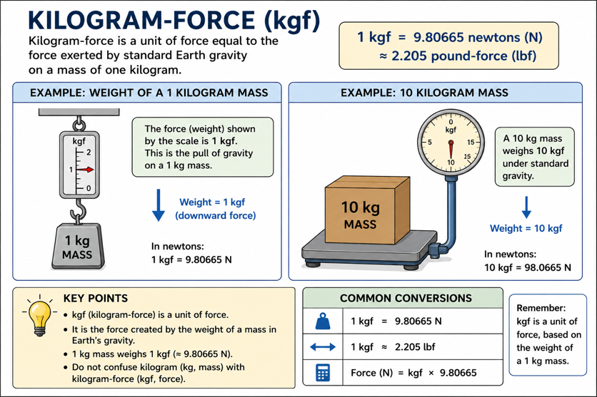
For example, an object with a mass of 10 kilograms exerts a downward force of approximately 10 kgf when it is resting near Earth’s surface. In newtons, that force is approximately 98.07 N. The relationship can be written as force in newtons equals kilogram-force multiplied by 9.80665.
In fastener and mechanical applications, kilogram-force may be used to describe clamp load, tensile load, pull-out force, test force, or the capacity of equipment. A fastener producing a clamp load of 1,000 kgf is pulling the joined parts together with a force of approximately 9,807 newtons.
Kilogram-force is not part of the modern International System of Units, which uses the newton as the standard unit of force. However, kgf is still encountered on older drawings, test equipment, pressure gauges, technical specifications, and machinery. In practical terms, kilogram-force tells you how strongly something is being pushed, pulled, lifted, stretched, or clamped, using the weight of a one-kilogram mass under standard gravity as the reference.
Kilonewton (kN)
Kilonewton, abbreviated kN, is a metric unit of force equal to 1,000 newtons. It is commonly used in engineering, construction, rigging, structural design, testing, and fastener applications to describe large forces without writing long numbers.
The conversion is:
1 kN = 1,000 N
A newton is the SI unit of force. One newton is the force needed to accelerate a 1-kilogram mass at 1 meter per second squared. So a kilonewton is simply one thousand of those units.
For rough practical comparison:
1 kN ≈ 224.8 pounds-force
10 kN ≈ 2,248 pounds-force
100 kN ≈ 22,480 pounds-force
In fastener and industrial applications, kilonewtons are often used to express tensile load, clamp load, proof load, shear load, breaking strength, test force, or working load. For example, a bolt, anchor, lifting component, or structural connector may be rated or tested in kilonewtons to show how much force it can withstand.
A kilonewton is similar in purpose to a kip, but from the metric side of the toolbox. A kip equals 1,000 pounds-force, while a kilonewton equals 1,000 newtons. For conversion:
1 kip ≈ 4.448 kN
1 kN ≈ 0.225 kip
In simple terms, a kilonewton is a clean metric way to talk about big forces. Instead of saying a fastener can handle 25,000 newtons, you can say it can handle 25 kN.
Kip
Kip is an engineering unit of force equal to 1,000 pounds-force. The word comes from “kilo-pound,” with “kilo” meaning one thousand. In structural, construction, mechanical, and fastener applications, kips are used as a convenient way to express large loads without writing lots of zeros.
For example, instead of saying a bolt is carrying 25,000 lb of tension, an engineer may say it is carrying 25 kips. The conversion is:
1 kip = 1,000 lbf
So:
10 kips = 10,000 lbf
50 kips = 50,000 lbf
0.5 kip = 500 lbf
In fastener and bolted-joint work, kips may be used to describe tensile load, clamp load, proof load, preload, shear load, structural load, or testing force. For example, a heavy structural bolt might be tested or specified by the number of kips it can carry before yielding, proof loading, or failure.
Kip is also closely related to ksi, which means kips per square inch. Since one kip equals 1,000 pounds-force, 1 ksi = 1,000 psi. So a steel with a tensile strength of 120 ksi has a tensile strength of 120,000 psi.
In simple terms, a kip is just a cleaner way to talk about big forces. Instead of saying “thirty-six thousand pounds of force,” you can say 36 kips and keep the math from looking like a runaway freight train.
Kips Per Square Inch (KSI)
Kips per square inch (KSI) is a unit of measurement used to express the strength of materials. One kip equals 1,000 pounds of force, meaning 1 ksi is equal to 1,000 pounds per square inch (psi). In the fastener industry, ksi is commonly used to specify mechanical properties such as tensile strength, yield strength, and proof load. For example, a fastener with a tensile strength of 60 ksi can withstand 60,000 pounds of force per square inch before failure.
Kitting
Kitting is the process of gathering multiple individual parts, fasteners, components, tools, labels, instructions, or packaging items into a single prepared set called a kit. Instead of picking each item separately at the point of use, the needed items are pre-counted, grouped, packaged, and organized so they are ready for assembly, installation, maintenance, shipping, or resale.
In manufacturing, kitting is often used to support production lines. For example, if an assembly requires six bolts, six washers, two nuts, one bracket, one spacer, and one instruction sheet, those items may be packaged together as one kit. The operator receives the complete set and can build the assembly without searching through bins or pulling each part separately. That reduces downtime, picking errors, missing parts, and clutter at the workstation.

In fastener distribution, kitting can be especially useful because assemblies often require many small, similar-looking parts. A fastener kit might include bolts, nuts, washers, lock washers, clips, pins, anchors, screws, spacers, or specialty hardware arranged by job, machine, repair procedure, customer part number, or bill of materials. Some kits are sealed in bags, boxed, compartmentalized, labeled with barcodes, or organized by installation step.
Kitting is also common in MRO, field service, aftermarket repairs, OEM production, construction, equipment maintenance, and VMI programs. For a maintenance technician, a kit can mean having every required fastener and component for a repair in one package. For a production team, it can mean fewer interruptions and better control over inventory. For a distributor, it can add value by turning many low-dollar parts into a convenient, customer-specific solution.
The main benefits of kitting are accuracy, speed, consistency, inventory control, and convenience. The main challenge is that the kit must be built correctly. If one part is missing, mislabeled, substituted incorrectly, or counted wrong, the whole kit can fail its purpose. Good kitting usually depends on accurate bills of materials, controlled picking, clear labeling, lot traceability when required, and quality checks before the kit is released.
KMC Clamp
A KMC clamp is a high-quality industrial fastening device produced by KMC, a company known for its durable clamps and clips since 1908. Their COV Series clamps are medium-duty, vinyl-coated clamps designed for securing wires and tubes at temperatures up to 300°F. KMC manufactures all standard parts in the USA, ensuring compliance with RoHS and REACH standards for industrial reliability.
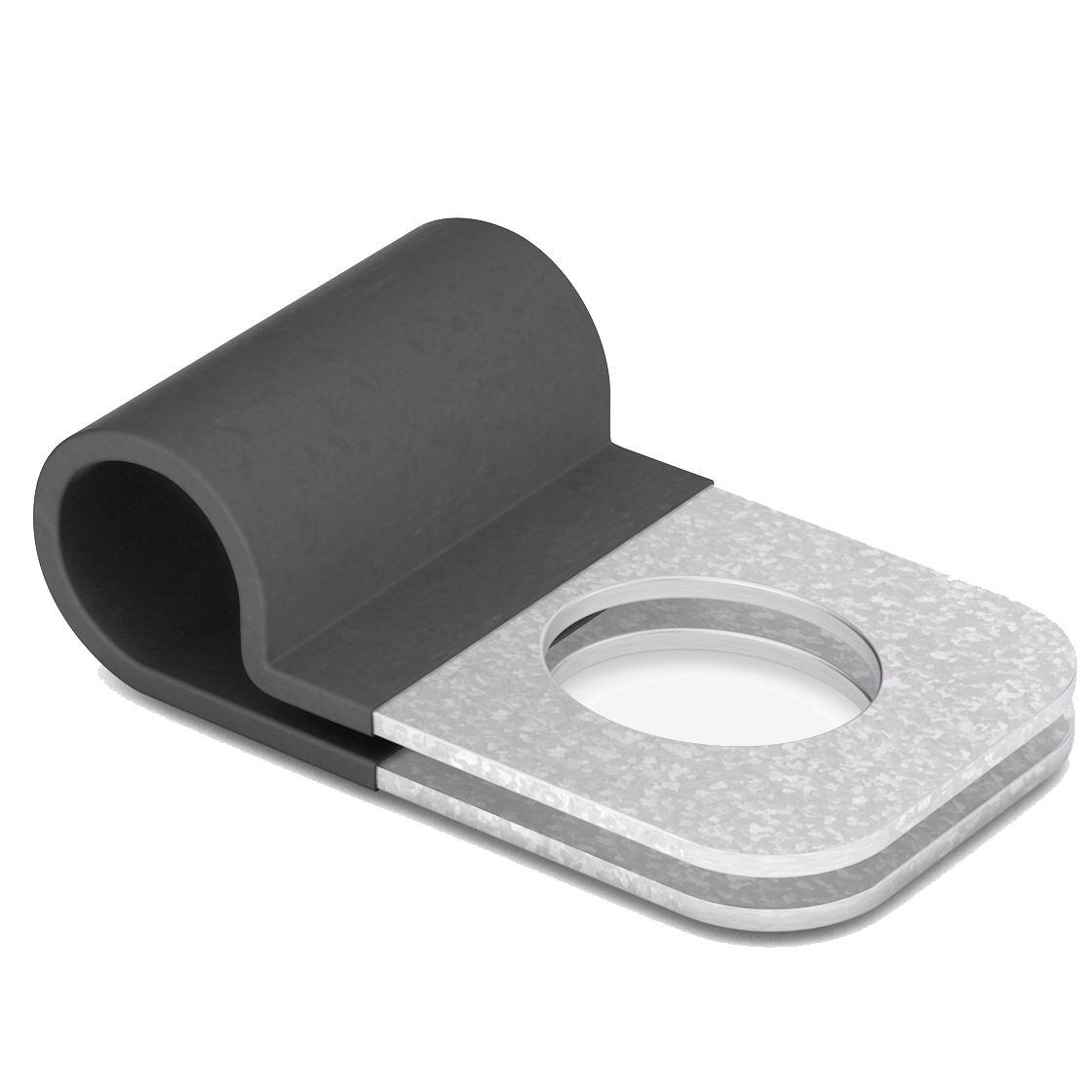
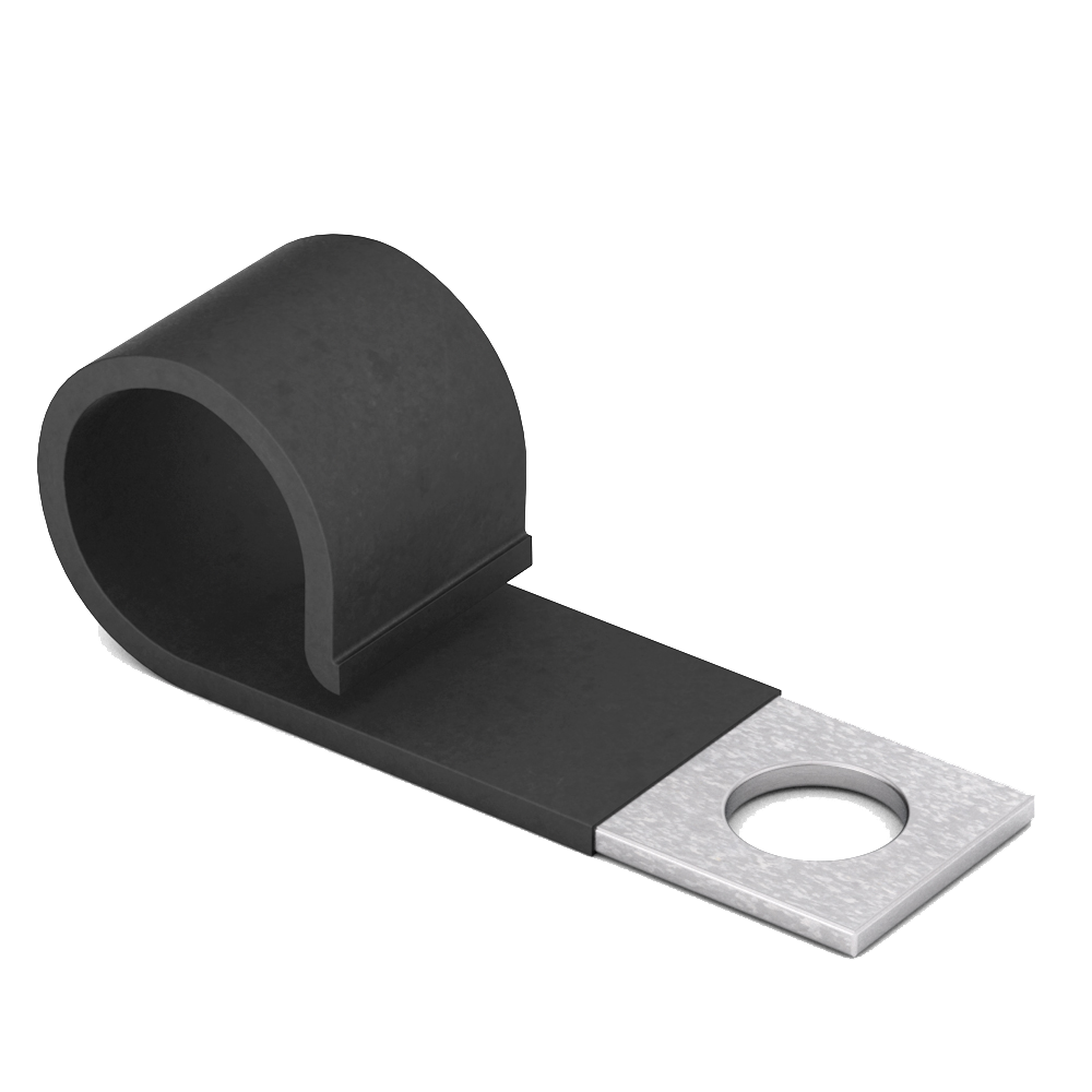
KMC Clip
A KMC clip is a fastening device produced by KMC, the Original Clip and Clamp Company established in 1908. These clips are designed to securely hold wires, cables, tubes, and pipes in various industrial applications. KMC offers a wide range of standard clips, such as the CJV Series, which are vinyl-cushioned tube and wiring clips available in various sizes to accommodate different clamping diameters. All standard catalog parts are made in the USA and comply with RoHS and REACH standards, ensuring high quality and reliability.
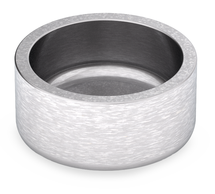
KMC Expansion Plug
An industrial expansion plug is a mechanical device used to seal, block, or test openings in pipes, tubes, or bores by expanding to create a tight and secure fit. These plugs are widely used in plumbing, automotive, aerospace, and industrial applications to prevent fluid or gas leakage, maintain pressure, or temporarily seal off sections for maintenance.
Knoop Hardness Test
The Knoop hardness test is a microhardness testing method used to measure the hardness of very small, thin, or delicate materials—such as metal coatings, thin films, ceramics, and microstructures—where traditional hardness tests (like Rockwell or Brinell) would be too aggressive or imprecise. It was developed by Frederick Knoop and his colleagues at the National Bureau of Standards in 1939.
Unlike macroscopic hardness tests that use larger loads and indenters, the Knoop test uses a very light load (typically between 10 and 1000 grams-force) and an elongated diamond-shaped indenter. The indenter is rhombohedral, with one diagonal much longer than the other (about a 7:1 ratio). This unique shape allows for shallow indentations, making it ideal for testing thin coatings or brittle materials without causing cracking or substrate influence.
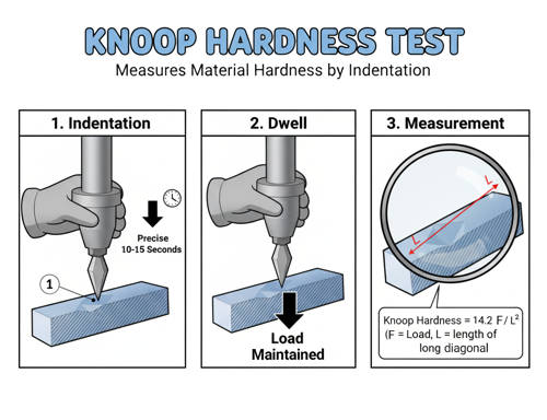
Here’s how the test works:
A highly polished sample surface is prepared, and the diamond indenter is pressed into it under a precise load for a set time (often around 10–15 seconds). After the load is removed, the length of the long diagonal (L) of the indentation is measured under a microscope. Because the indentation is so shallow, the area of contact can be accurately calculated using that diagonal measurement.
The Knoop hardness number (HK) is then determined by the formula:
HK = 14.229 × (F / L²)
where:
- HK = Knoop hardness number
- F = applied load (in kilograms-force)
- L = length of the long diagonal (in millimeters)
The constant 14.229 is derived from the geometry of the indenter.
The resulting value is expressed in kgf/mm² and gives a precise indication of the material’s resistance to localized deformation.
Because the Knoop test causes minimal surface damage and offers extremely fine resolution, it’s commonly used in metallurgy, thin-film coatings, microelectronics, ceramics, and glass. It’s particularly useful for measuring hardness gradients in surface treatments, case-hardened steels, and individual microstructures or phases within a metal or alloy.
Knurl
A knurl on a fastener is a patterned ridge texture—usually straight, diamond (cross-hatched), or helical—formed by rolling or cutting the metal. It’s added to the shank, head, or flange to create friction or an interference fit so the part won’t rotate or pull out. You’ll see knurls on press-fit pins, self-clinching/press-in nuts and inserts (especially for plastics and soft metals), rivet nuts with anti-rotation bands, and on thumb screws/knobs where the pattern also improves finger grip.
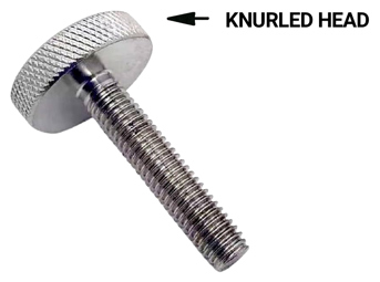
Compared with under-head serrations (which lock under a bolt head), knurls are raised ridges that bite into a mating material along the surface they contact. The result is higher torque-to-turn resistance, better anti-rotation in plastics and aluminum, and more reliable retention without adhesives.
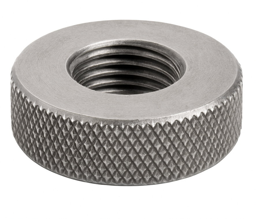
Knurled Nut
A knurled nut is a specialized fastener with a ridged or textured exterior surface—called knurling—that enhances grip for hand tightening and loosening without tools. Unlike conventional nuts that depend on wrenches or sockets, knurled nuts are designed for applications where quick adjustments, easy assembly, or frequent removal are needed. This makes them especially useful in settings where convenience and accessibility are prioritized over high clamping force.
In terms of design, knurled nuts are often cylindrical, but they can also take flanged or domed forms. The knurling pattern, which may be straight, cross-hatched, or diamond-shaped, is either machined or rolled into the nut’s surface to create a roughened grip. These nuts are produced in various materials—such as brass for conductivity, stainless steel for corrosion resistance, aluminum for lightweight strength, and plastic for cost efficiency or non-conductive applications—depending on the performance requirements of the assembly.
The purpose of a knurled nut is to enable secure fastening while still allowing tool-free operation. They are intended for low-torque applications where a firm hand grip is sufficient, making them ideal for adjustments, fine positioning, or parts that require frequent disassembly. Their hand-friendly design ensures users can easily operate them even in tight or delicate setups, where over-tightening with tools could cause damage.
Common applications include electronics, instrumentation, and machinery, where they secure panels, covers, or knobs. They are also prevalent in camera and lighting equipment, which often demand rapid hand adjustments, as well as in furniture assembly, consumer appliances, and clamping systems where tool-free operation is a key advantage.
Knurled nuts offer several benefits: they are simple to install and remove, provide excellent grip even with oily or wet hands, are available in multiple materials and finishes to suit specific uses, and eliminate the need for tools in many low-torque assemblies. However, they do have limitations. They are unsuitable for high-load or high-vibration environments, where the absence of strong clamping force can cause loosening. Over time, the textured edges can wear down, especially with frequent adjustments, and some designs are bulkier compared to standard nuts, making them less space-efficient.
Kroll Process
The Kroll process is the primary industrial method for producing titanium metal from its ore. It is a multi-step chemical reduction process that converts titanium dioxide (TiO₂) into pure metallic titanium (Ti) using magnesium (Mg) as a reducing agent. Developed by Dr. William J. Kroll in the 1940s, this process remains the dominant technique for titanium production worldwide due to its reliability and ability to produce high-purity metal.
The process begins with titanium dioxide (TiO₂)—extracted from ores such as ilmenite (FeTiO₃) or rutile (TiO₂)—which is first converted into titanium tetrachloride (TiCl₄), also known as “tickle”, through chlorination. In this step, TiO₂ reacts with chlorine gas and a carbon source (often coke) at high temperatures (around 900°C):
TiO₂ + 2Cl₂ + C → TiCl₄ + CO₂
The titanium tetrachloride, a volatile liquid, is then purified by distillation to remove impurities like iron, vanadium, and silicon. This purified TiCl₄ is then fed into a reduction reactor, typically made of steel, where it reacts with molten magnesium at around 800–900°C in an inert argon atmosphere. The reaction converts the titanium chloride into metallic titanium and magnesium chloride:
TiCl₄ + 2Mg → Ti + 2MgCl₂
The titanium produced in this step is not molten but forms as a spongy, porous mass known as titanium sponge. After cooling, the solidified mixture of titanium and magnesium chloride is crushed and leached or vacuum-distilled to remove residual magnesium and MgCl₂, leaving behind nearly pure titanium metal. The resulting sponge can then be melted, alloyed, or forged into bars, sheets, or billets for aerospace, chemical, and industrial applications.
Despite being energy-intensive and relatively slow, the Kroll process produces high-quality titanium suitable for critical uses such as aerospace components, medical implants, and corrosion-resistant equipment. It has largely replaced the older Hunter process, which used sodium as a reducing agent.